
A parking lot photometric plan is more than a colored grid on a drawing. It is the document that proves your exterior lighting meets safety, code, and owner expectations.
This guide explains how to read and design a parking lot lighting plan, what uniformity ratios mean, and which requirements matter most for architects, engineers, and contractors. A parking lot photometric plan is often required for permits and inspections, and it must be prepared accurately to meet local lighting codes and safety standards. If you need a professional photometric plan, Stetra Lighting provides permit-ready calculations for parking lots and site lighting.
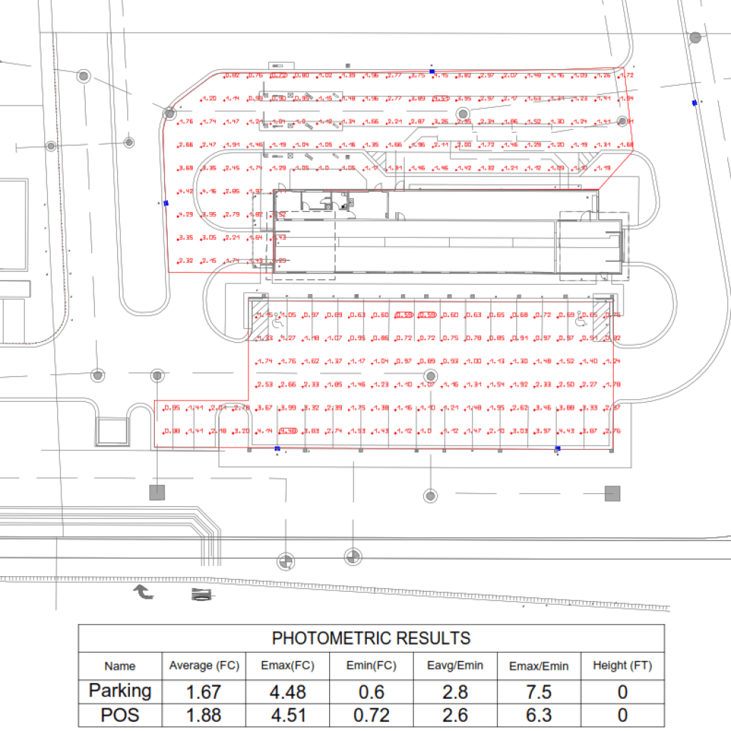
Why a Parking Lot Photometric Plan Matters
Most lighting issues in parking lots start with an incomplete or low-quality design. Once poles are installed, fixing dark spots, glare, or neighbour complaints becomes expensive. A proper photometric plan helps you catch problems on screen before they appear on site.
See Lighting Performance Before Construction
A photometric study lets you check light levels, uniformity, and spill light before any pole is ordered. Instead of guessing, you can show the owner and the authority having jurisdiction (AHJ) exactly how the lighting will perform at night. Fixture distribution and light patterns can be reviewed using an IES file viewer before finalizing the layout.
- Confirm minimum and average foot-candle levels for drive lanes and parking stalls based on recommended foot-candle levels for parking lots.
- Review uniformity ratios so there are no harsh transitions between bright and dark zones.
- Check light trespass and glare at property lines, neighboring buildings, and roadways.
For owners, a clean photometric plan builds confidence that their parking lot will feel safe and easy to navigate at night. For designers, it is the technical proof that fixture selection, pole heights, and spacing are correct as part of professional lighting design services.
Key Metrics in a Parking Lot Photometric Plan
Every parking lot design should clearly show light levels and ratios. These metrics tell you if the layout is both comfortable and code-compliant. Most U.S. projects use foot-candles (fc) at grade to describe horizontal illuminance.
- Average foot-candles (Avg FC) – the overall brightness level across the calculation area.
- Minimum foot-candles (Min FC) – the darkest points on the grid, critical for safety and visibility.
- Max FC – the brightest points, which can cause discomfort or glare if too high.
- Uniformity ratios – typically Avg:Min and Max:Min, used by many standards and AHJs.
- Calculation areas – separate grids for parking bays, drive aisles, entrances, and sometimes walkways.
Many designers reference Illuminating Engineering Society guidance when setting targets, but the final criteria should always be checked against the project requirements and the authority having jurisdiction.
Uniformity Ratios, Light Levels, and Glare Control
Uniformity ratios describe how even the lighting is across the lot. A good parking lot photometric plan balances average and minimum illumination, contrast, glare control, and the criteria that apply to the specific site.
- Avg:Min ratio – ratios around 3:1–4:1 are commonly used as design targets on many projects.
- Max:Min ratio – ratios below approximately 10:1 are often desirable for controlling excessive contrast.
- Glare and BUG ratings – shielding, optics, cutoff, aiming, and BUG performance may be reviewed depending on the project and local ordinance.
| Item | Common Design Range / Example | What to Verify |
|---|---|---|
| Average Light Level | Often approximately 0.8–2.0 fc for general parking areas | Confirm the project criteria and local AHJ requirements. |
| Minimum Light Level | Project-specific | Verify required minimums for parking areas, drive aisles, pedestrian routes, and other calculation zones. |
| Drive Lanes | Often designed at higher levels than low-activity parking areas | Confirm roadway, pedestrian, and site-specific requirements. |
| Pedestrian Paths | Project-specific | Check accessible routes, entrances, sidewalks, and local code requirements. |
| Avg:Min Uniformity | Ratios around 3:1–4:1 are commonly used as design targets on many projects | The required ratio varies by application, owner criteria, and jurisdiction. |
| Max:Min Uniformity | Ratios below approximately 10:1 are often desirable for controlling excessive contrast | Always verify the governing standard or AHJ criteria. |
| Glare Control | BUG rating, shielding, cutoff, optics, and aiming may be reviewed | Requirements depend on the lighting zone and local ordinance. |
| Property-Line Spill Light | Limits are frequently specified by the local jurisdiction | Residential boundaries and environmentally sensitive areas may have stricter limits. |
| Pole Height | Commonly selected based on site size, fixture distribution, setbacks, and local restrictions | Verify maximum permitted pole height and shielding requirements. |
| Calculation Grid | Grid spacing should be appropriate for the project and reviewing authority | Some jurisdictions or project standards specify calculation-point spacing. |
Important: These values are general design references, not universal code requirements. Parking-lot lighting criteria vary by municipality, zoning district, project type, surrounding properties, and the authority having jurisdiction (AHJ). Always verify the requirements that apply to the specific project before finalizing the photometric plan.
What Should a Parking Lot Photometric Plan Include?
A professional parking lot photometric plan should clearly show both the lighting layout and the calculated performance of the proposed fixtures. For permitting and design review, the drawing should make it easy for the owner, contractor, engineer, and authority having jurisdiction to understand how the site will perform before installation.
A typical parking lot photometric plan may include:
- Fixture locations and pole locations showing where each luminaire will be installed.
- Fixture schedule identifying the manufacturer, model, lumen output, wattage, optics, CCT, mounting height, and other relevant specifications.
- Point-by-point foot-candle calculations showing the predicted illumination throughout the parking area, drive aisles, pedestrian routes, entrances, and other required zones.
- Minimum, maximum, and average light levels for each calculation area.
- Uniformity ratios, such as Avg:Min and Max:Min, where required.
- Property-line calculations to evaluate light trespass onto neighboring properties.
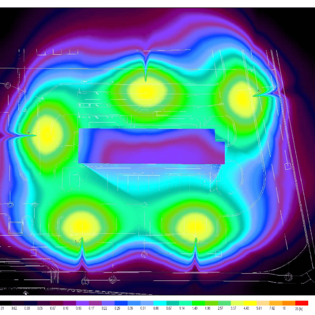
- Iso-footcandle contours or false-color analysis when useful for showing how the light is distributed across the site.
- Glare and spill-light considerations, including shielding, fixture distribution, BUG ratings, and aiming where applicable.
- Project notes and design assumptions such as mounting heights, calculation-plane height, fixture output, and applicable local requirements.
The exact information required varies from project to project. For permit submissions, the local municipality or authority having jurisdiction should always be checked before the final calculation is issued.
At Stetra Lighting, we prepare parking lot photometric plans using manufacturer photometric data and project-specific site information so the lighting layout can be evaluated before poles and fixtures are installed.
When Stetra Lighting prepares a parking lot photometric plan, we test several layouts and distribution types. The goal is to meet project standards with as few poles as practical while keeping the site comfortable, legible, and neighbor-friendly.
For a broader explanation of the drawing itself, see our guide to what a photometric plan is. If you need to review an existing plan, use our step-by-step guide on how to read a photometric plan.
Example: Fixing a Poor Parking Lot Layout
To see how this process changes a project, it helps to look at a real scenario. Many projects come to us after the first layout fails to meet either the owner’s expectations or the city requirements.
- Project / context: Medium-size retail parking lot with 25 ft poles and area lights on a 1:1 spacing pattern, designed only from a catalog cut sheet.
- Challenge: The initial study showed dark corners, high contrast near the main entrance, and Max:Min ratios exceeding 20:1 in some drive lanes.
- Result: After revising the parking lot photometric plan, adjusting pole locations, and changing optics, we achieved target average light levels with an Avg:Min ratio under 4:1 and Max:Min below 10:1, while using the same fixture family.
- Extra benefit: The updated design reduced energy use by removing two poles and optimizing light distribution instead of simply adding more wattage.
This kind of optimization is only possible when the plan is treated as a design tool, not just a permit drawing. It lets the whole team see the impact of every pole shift, tilt angle, and lumen package change.
Key Takeaways for Parking Lot Photometric Plans
A strong parking lot design starts with a clear, well-documented photometric plan. When you understand light levels, uniformity ratios, and how fixtures actually distribute light on the ground, you avoid surprises after installation.
| Requirement | U.S. Standard / Typical Value | Description |
|---|---|---|
| Average Light Level (Avg FC) | 0.8 – 2.0 fc | Typical IES RP-8 recommendation for general parking areas. |
| Minimum Light Level (Min FC) | 0.2 fc | Lowest acceptable value for safe visibility in most U.S. parking lots. |
| Drive Lanes – Avg FC | 1.0 – 2.5 fc | Higher illumination helps drivers identify pedestrians and vehicles. |
| Pedestrian Paths – Min FC | 0.5 fc | Areas where people walk require stronger visibility. |
| Avg:Min Uniformity Ratio | 3:1 – 4:1 | Standard for comfortable, even lighting without dark patches. |
| Max:Min Uniformity Ratio | ≤ 10:1 | Prevents harsh contrast between bright and dark zones. |
| Glare Control | BUG Rating per TM-15 | Most municipalities require controlled uplight and backlight near property lines. |
| Property Line Limit | 0.1 – 0.5 fc (AHJ-specific) | Light trespass limits along neighboring lots or residential areas. |
| Pole Height | 20 – 30 ft typical | Selected to balance uniformity, distribution, and glare. |
| Calculation Grid | 10 ft spacing | Standard grid resolution for parking lot photometric plans. |
Before you order fixtures or pour foundations, make sure your parking lot photometric plan has the right targets, ratios, and calculations in place. If you need support, Stetra Lighting can prepare a professional, permit-ready design tailored to your site, fixtures, and local requirements.