

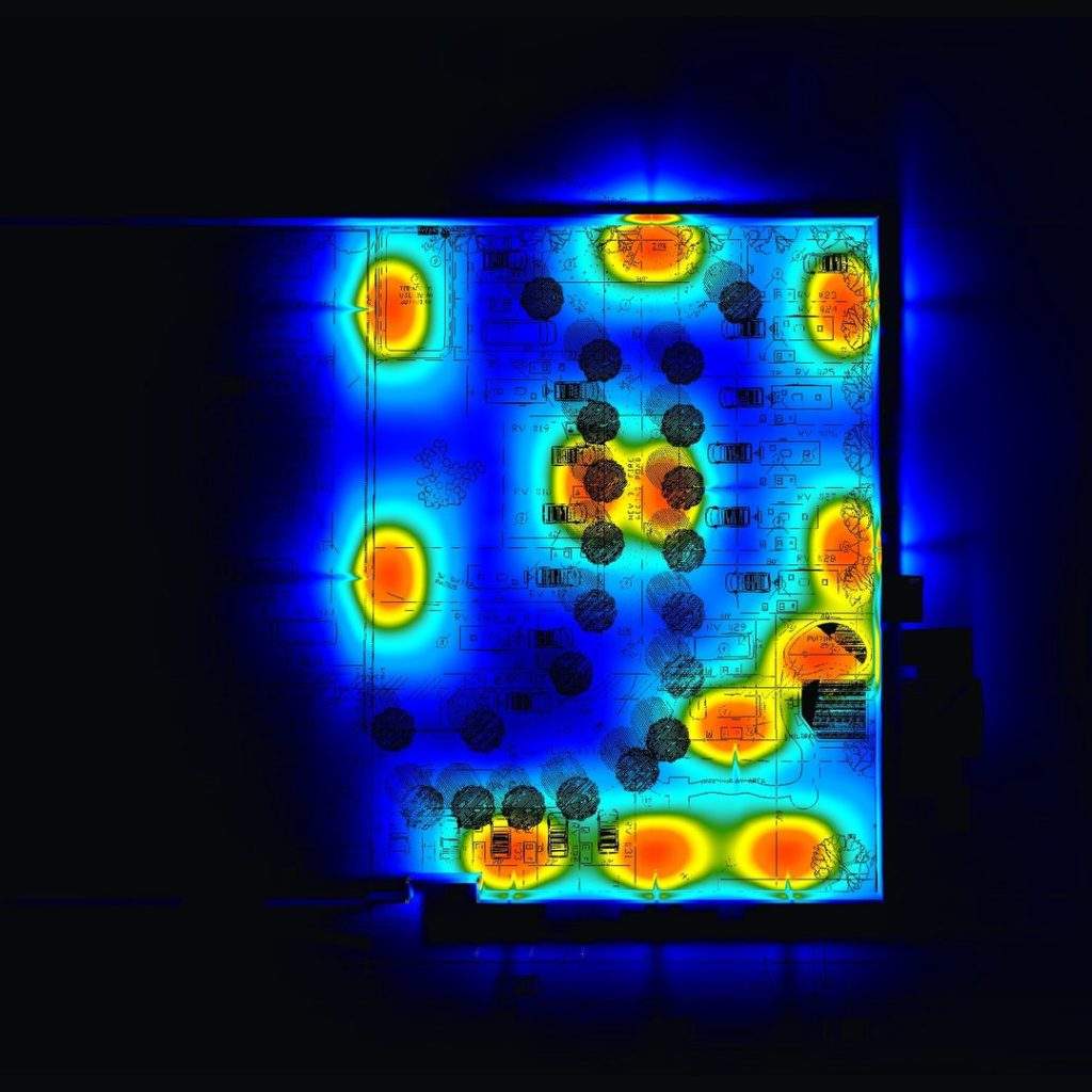
Can seven solar poles light a parking lot well? And can solar lights illuminate an RV park without sending too much light toward the neighbors?
Those were practical questions behind two projects supplied to Stetra Lighting. Both started with a proposed solar lighting layout. The calculations reveal why choosing a fixture and counting poles are only part of the job.
A solar lighting photometric plan predicts where light will fall, how bright different areas will be, and how much light reaches the site boundary. It uses the fixture’s photometric data, mounting details and site geometry. Battery runtime needs a separate check.
Below, we look at what the two reports show and what a similar project team should confirm before ordering fixtures. If you are new to the deliverable, start with our guide to what a photometric plan includes.
Seven solar poles: look beyond the average
The parking lot enquiry proposed seven solar post lights and asked for a recommendation on the minimum number of poles. That is a useful question to ask before buying equipment: each pole needs a location, a foundation and a fixture that can cover the intended area.
The supplied report models seven luminaires at 75 W and 8,545 lumens each. Its parking-area summary gives the following calculated results. A foot-candle, abbreviated fc, measures the light reaching a surface.
| Parking-area result | Reported value |
|---|---|
| Average illuminance | 2.34 fc |
| Maximum illuminance | 8.49 fc |
| Minimum illuminance | 0.10 fc |
| Average-to-minimum ratio | 23.40:1 |
| Maximum-to-minimum ratio | 84.90:1 |
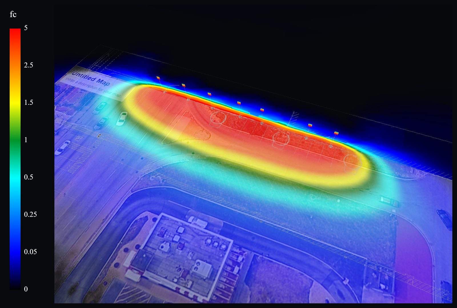
The average tells you something useful, but it cannot tell you whether the darker parts of the lot receive enough light. Here, the reported average is more than 23 times the minimum. The layout deserves a closer look at the low points and the areas people will actually use.
That does not establish that the plan fails a requirement. The applicable minimum levels, uniformity criteria and calculation areas must be identified first. It does show why accepting a layout on its average alone can overlook a problem.
If the low points need improvement, the next step is to test changes to pole positions, mounting height, optics or fixture output. Additional poles are another option. Each change needs recalculation; this report contains one layout, so it does not prove which alternative would work best.
Our lighting uniformity guide explains how to read these ratios. For this example, the useful takeaway is simple: ask where the minimum occurs before deciding whether seven poles are enough.
An RV park: check the edges as well as the roads
The RV park brief included solar yard lights and separate attached lights that would not be solar. It also identified a pickleball court, putting green and children’s play area. The owner asked for shielded lighting, a maximum color temperature of 3000 K, and checks at neighboring properties and toward the highway.
Those requests make the scope more specific than a general site average. Internal roads, walking routes, amenities and property boundaries need to be considered in their own context.
The report schedules 12 pole luminaires at 13 ft and three frosted globe post lights at 8 ft. Both entries list 3000 K, zero tilt and a light-loss factor of 0.90. These are documented calculation inputs; the schedule alone does not verify the installed products or their operating settings.
| Calculation area | Average | Maximum | Minimum |
|---|---|---|---|
| Site | 0.39 fc | 9.46 fc | 0 fc |
| Proposed expansion | 1.46 fc | 9.78 fc | 0.041 fc |
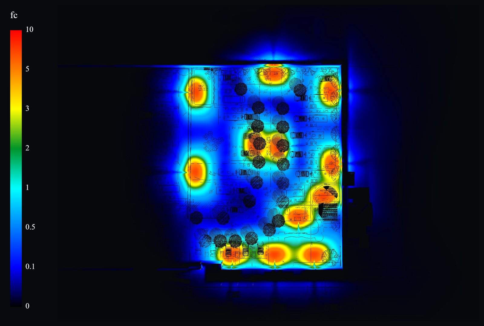
The proposed expansion has a reported average-to-minimum ratio of 35.61:1. Before interpreting that number, check the calculation boundary: does it include spaces intended to remain dark, or areas that need usable lighting? A broad site summary cannot establish the suitability of an individual walking route or pickleball court.
What does the boundary result mean?
The report’s light-trespass panel displays a maximum of 0.10 fc at 0 ft against an entered allowance of 0.10 fc. At the displayed precision, the result sits at the entered limit.
This is a useful point to review before the layout is finalized. Confirm the unrounded result, calculation-plane orientation, boundary coverage and source of the allowance. A rounded value at the limit gives little visible margin for a fixture or mounting change.
The panel does not establish zero spill, the absence of glare toward the highway, or approval by the local authority. Those questions need their own supporting checks. Ground-level illuminance and glare toward a driver are different things.
Planning a similar site? Request a project-specific photometric quote and include the site drawing, proposed fixtures and any boundary or roadway review comments.
Both reports list a light-loss factor of 0.90. The values here are simulated report results, not measurements after installation. Confirm the calculation-plane elevations and maintenance assumptions when assessing the final design.
Make sure the fixture data match the operating mode
A solar light may run at full output when motion is detected, then dim after a delay. It may also offer several color-temperature settings. The calculation needs to represent the setting the project will actually use.
In the RV park correspondence, the owner specifically asked for confirmation that a proposed product could remain at 3000 K in every operating mode, with matching photometric data. The report lists 3000 K, but the supplied files do not establish that the manufacturer confirmed that behavior.
Resolve that distinction before specifying the product. Ask for the exact model, optic, output setting, color temperature and IES file. An IES file describes how a fixture distributes light in different directions; a wattage or total-lumen figure cannot replace it.
If overnight dimming is part of the design, agree which operating conditions need calculation. A full-output layout does not show the light levels after dimming. Where output changes without a distribution change, a documented output adjustment may be appropriate; where the distribution changes, matching photometric data are needed.
Check solar runtime separately
A lighting calculation can show the predicted illuminance at a stated output. It cannot establish how long the battery will sustain that output through the night or after cloudy weather.
Ask the system supplier to check panel capacity, battery capacity, shading, local solar conditions and the nightly operating schedule. The U.S. Department of Energy’s solar street and area lighting fact sheet explains why available solar energy and the duration of lighting demand matter when evaluating these systems.
Keep the two checks connected. If the battery design relies on dimming for part of the night, the project team should understand the lighting performance during that period too.
What to send for your solar lighting plan
A useful starting package includes:
- A scaled site plan with property lines, roads, buildings and the areas that need lighting.
- Proposed pole positions and luminaire mounting heights, or a request to develop a layout.
- The fixture specification sheet, exact model and matching IES file, where available.
- The intended output, dimming schedule and color-temperature settings.
- Project criteria and any comments from the reviewing authority.
- Nearby homes, roads or other locations where spill light or glare needs attention.
Tell the designer which decision you need to make. “Can these seven poles cover the parking area?” gives the study a clear purpose. So does “What reaches the property line with this fixture?”
When the report arrives, review the calculation areas, minimum values and assumptions alongside the images. Our guide to reading a photometric plan walks through those checks.
Get a solar lighting layout checked before you order
The parking lot example shows why the average needs context. The RV park example shows why fixture settings and boundary checks deserve attention early. Both help turn a proposed arrangement of lights into specific questions the project team can resolve.
Stetra Lighting can review your drawings, proposed fixtures and calculation requirements to define the scope of a photometric plan.
Request a solar lighting photometric plan quote. Tell us what you are planning and which lighting questions need answering.