A photometric plan is a technical lighting document that shows how light is distributed across a space.
It is used by lighting designers, engineers, and code officials to verify that a lighting system meets required performance, safety, and visibility standards.
Photometric plans are based on real fixture data (IES files) and calculated using professional lighting software.
They are required for many commercial, industrial, and outdoor projects before permits are approved.
This guide explains what a photometric plan is, what it includes, how it is created, and why it is required.
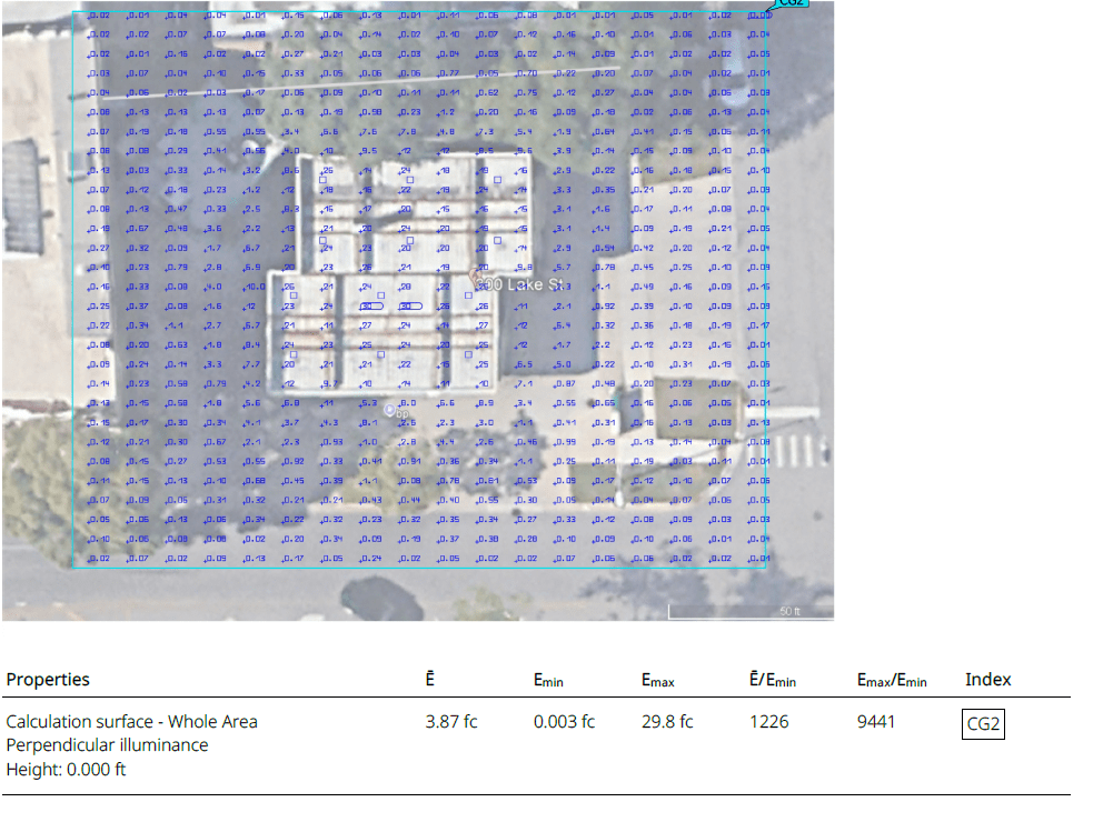
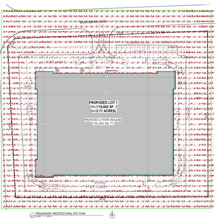
Example of a photometric plan with foot-candle grid used for lighting design and permit approval.This photometric plan illustrates how foot-candle values are distributed across a site.
Lighting designers and code officials use this type of calculation to verify compliance with visibility and safety requirements.
What Is a Photometric Plan?
A photometric plan is a drawing that visually represents light levels across a defined area.
It shows how much light reaches the ground, floor, or working surface from installed fixtures.
A standard photometric plan displays:
- Light levels in foot-candles (fc) or lux
- Fixture locations and mounting heights
- Uniformity ratios
- Dark zones and overlaps
Designers use photometric plans to adjust fixture spacing, optics, and quantities to achieve consistent and code-compliant lighting.
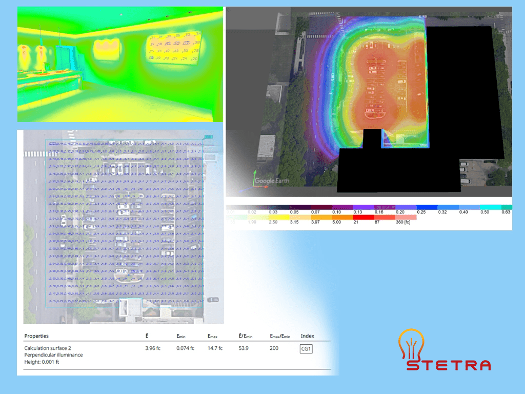
Photometric analysis using false-color visualization to evaluate light distribution.Ready to optimize your lighting project with precision and efficiency? Click the button below to get started!
Order Your Photometric PlanWhat a Professional Photometric Plan Includes for Permits
Fixture Schedule: This includes a detailed list of all lighting fixtures, each linked to the manufacturer’s IES (Illuminating Engineering Society) files, ensuring that the performance specifications are met as per the design intent.
Calculated Light Levels: Light levels are meticulously calculated and presented on a defined grid, providing a clear visual representation of the illumination distribution across the area.
Foot-Candle Values: The plan outlines the average, minimum, and maximum foot-candle values, offering insights into the intensity of light in various sections and ensuring it aligns with the project requirements.
Uniformity Ratios: These ratios, which are mandated by the relevant codes, show the consistency of light distribution, ensuring safety and visibility in the illuminated area.
Notes for Inspectors and Plan Reviewers: Detailed annotations are included to guide inspectors and reviewers through the plan, highlighting compliance with codes and any special considerations or requirements.
Additional Elements for Outdoor Projects:
- Property Lines: Clearly marked boundaries ensure that the lighting design respects property limits and complies with zoning regulations.
- Light Trespass Limits: The plan specifies limits to prevent light from spilling over into adjacent properties, minimizing disturbance and complaints.
- Spill and Glare Control: Measures are outlined to control unwanted spill and glare, enhancing visual comfort and reducing potential hazards.
Such detailed documentation is what cities, engineers, and contractors anticipate when assessing a photometric plan, ensuring that all aspects of the lighting design meet the necessary regulatory and safety standards.
Expediting Project Approval
Submitting an accurate and comprehensive photometric plan is essential for an efficient permit review process. Without this documentation, a project can be delayed while officials request additional information to confirm it meets code.
A photometric plan translates the design concept into the language of compliance, giving inspectors and city planners the evidence needed to approve a project confidently. For projects requiring municipal approval, Stetra Lighting provides the necessary technical documentation. When you order a permit-ready photometric plan, you receive an analysis engineered to satisfy code requirements and facilitate a smoother approval process.
Process of Creating Photometric Plans by Designers
Designers employ a systematic approach to develop precise and dependable photometric plans. Here’s an in-depth look at the process:
Understanding the Space
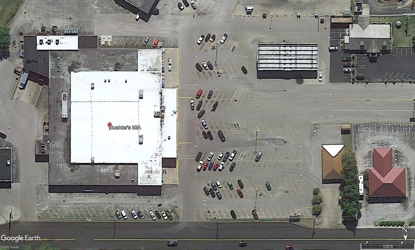
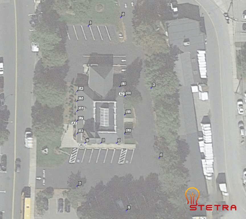
Initially, designers gather detailed information about the space’s layout, dimensions, and intended use. For outdoor settings such as parking lots or site lighting, they utilize scaled aerial images or CAD site plans to gain a comprehensive view.
Determining Lighting Requirements
The next step involves defining the necessary light levels, which are influenced by several factors:
- The specific function of the space
- Adherence to safety standards
- Compliance with local regulations and Illuminating Engineering Society (IES) guidelines
These considerations help establish target foot-candles, uniformity ratios, and glare limits.
Selecting Appropriate Fixtures
Designers choose fixtures based on various criteria:
- The height at which they will be mounted
- The beam angle and light distribution pattern
- The overall output and efficiency of the fixture
Each fixture’s photometric data, contained in an IES file, plays a crucial role in determining how light is distributed throughout the site.
Utilizing Photometric Software
Lighting design software is employed to simulate how light will disperse, taking into account the placement of fixtures and their photometric characteristics. This phase results in the creation of the actual photometric plan.
Analyzing and Adjusting Results
Finally, designers evaluate the generated results and make necessary adjustments to fixture spacing, optics, or quantities. This iterative process continues until the desired performance targets are achieved.
Which Software Is Used to Create Photometric Plans?
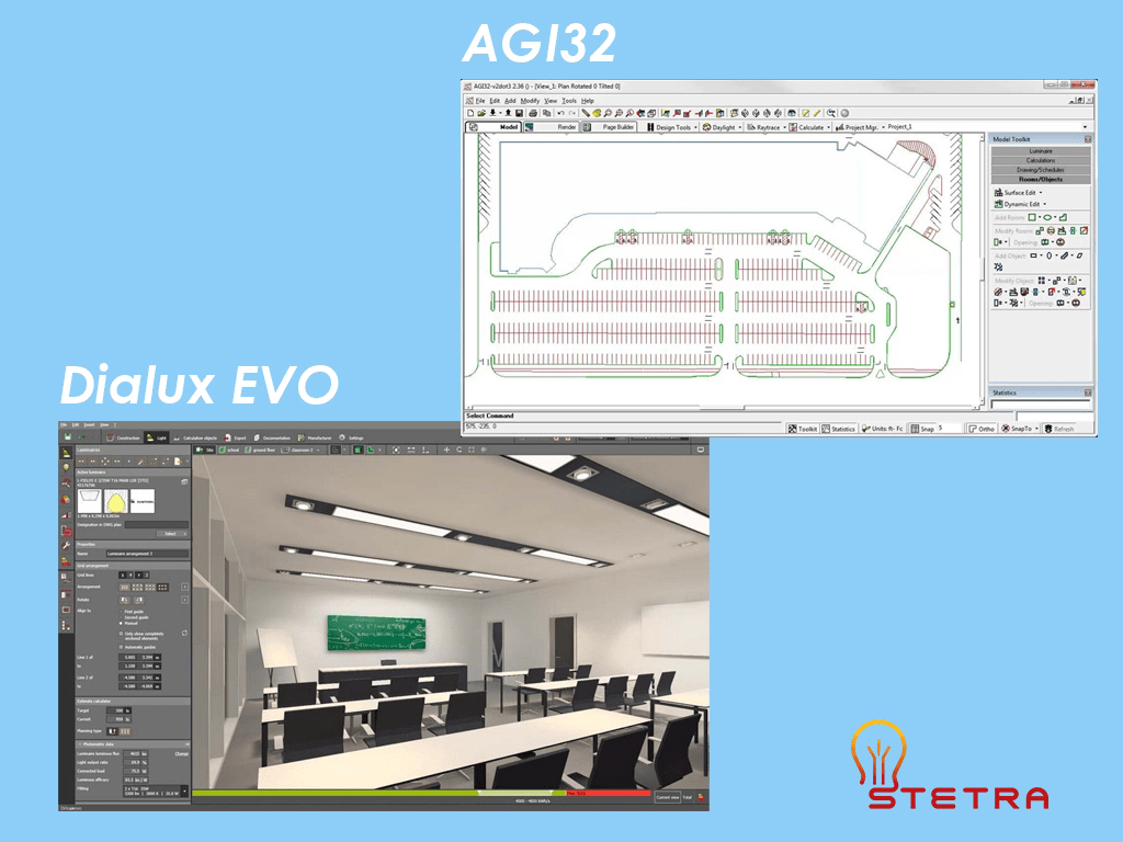
Two of the most widely used lighting software tools are DIALux EVO and AGi32.
- DIALux EVO
Free software with an intuitive interface, widely used for architectural and site lighting. - AGi32
Professional-grade software with advanced calculation control and detailed analysis tools.
Both programs use IES photometric data and produce code-compliant photometric plans when used correctly.
DIALux EVO and AGi32 are widely used lighting software programs for designing and analyzing lighting plans. In practice, each tool serves a different type of user. As a result, they differ in several key areas.
1. User Interface
First, DIALux EVO offers a user-friendly interface that designers can navigate easily, which makes it suitable for beginners. By contrast, AGi32 provides a more advanced interface and requires technical knowledge to operate effectively.
2. Calculation Capabilities
In both cases, the software uses photometric technology to calculate light distribution within a space. However, AGi32 supports more advanced calculations. Because of this, designers can run more detailed simulations and perform deeper analysis.
3. Fixture Libraries
In terms of fixture data, AGi32 includes a larger library of lighting fixtures, materials, and photometric files. Meanwhile, DIALux EVO provides a comprehensive library, but it offers fewer fixture options overall.
4. Pricing
From a cost perspective, DIALux EVO is available as a free program. By comparison, AGi32 requires a paid license, with pricing based on the license type and selected features.
How to read a photometric plan
A photometric plan contains several key elements that designers and inspectors review.
1. Lighting Layout
This shows fixture locations, mounting heights, and coverage areas.
Designers position fixtures to achieve even illumination and avoid dark spots.
2. 3D Presentation
3D views help visualize how lighting will appear once installed. In addition, they are useful for coordination; however, they do not replace calculated results.
One of the key benefits of a 3D presentation of a light plan is that it allows designers to see how lighting interacts with the space and other design elements, such as furniture or architecture. As a result, designers can identify potential issues early. In turn, this enables them to make necessary adjustments before installation, which helps prevent problems during fixture installation.
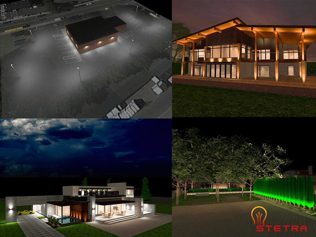
3D lighting render used to visualize lighting design before installation.While 3D lighting presentations help visualize how a project will look once installed, they are not used for lighting verification or permit approval.
Photometric plans and false-color analysis provide the calculated data required to evaluate light levels, uniformity, and code compliance. These technical documents show measured illuminance values across the site and are used by engineers, inspectors, and authorities to confirm that lighting performance meets project requirements.
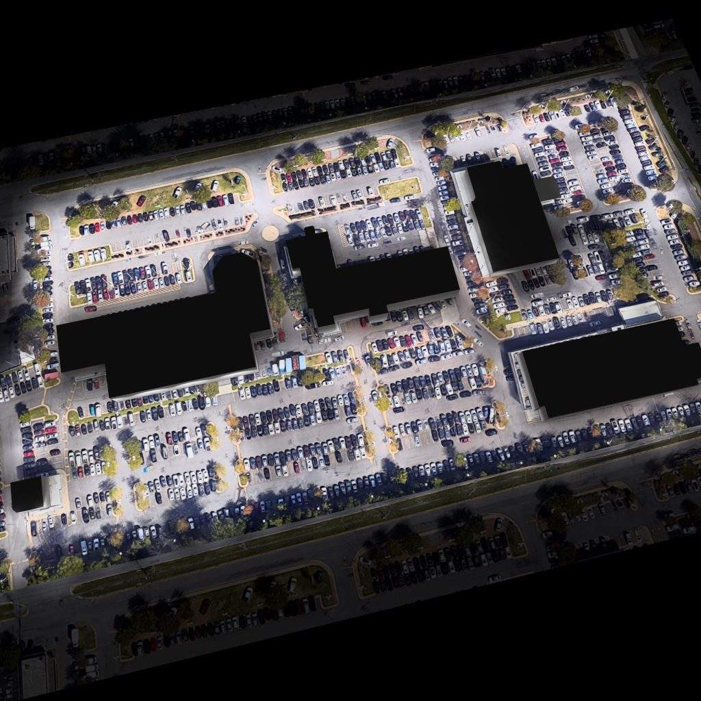
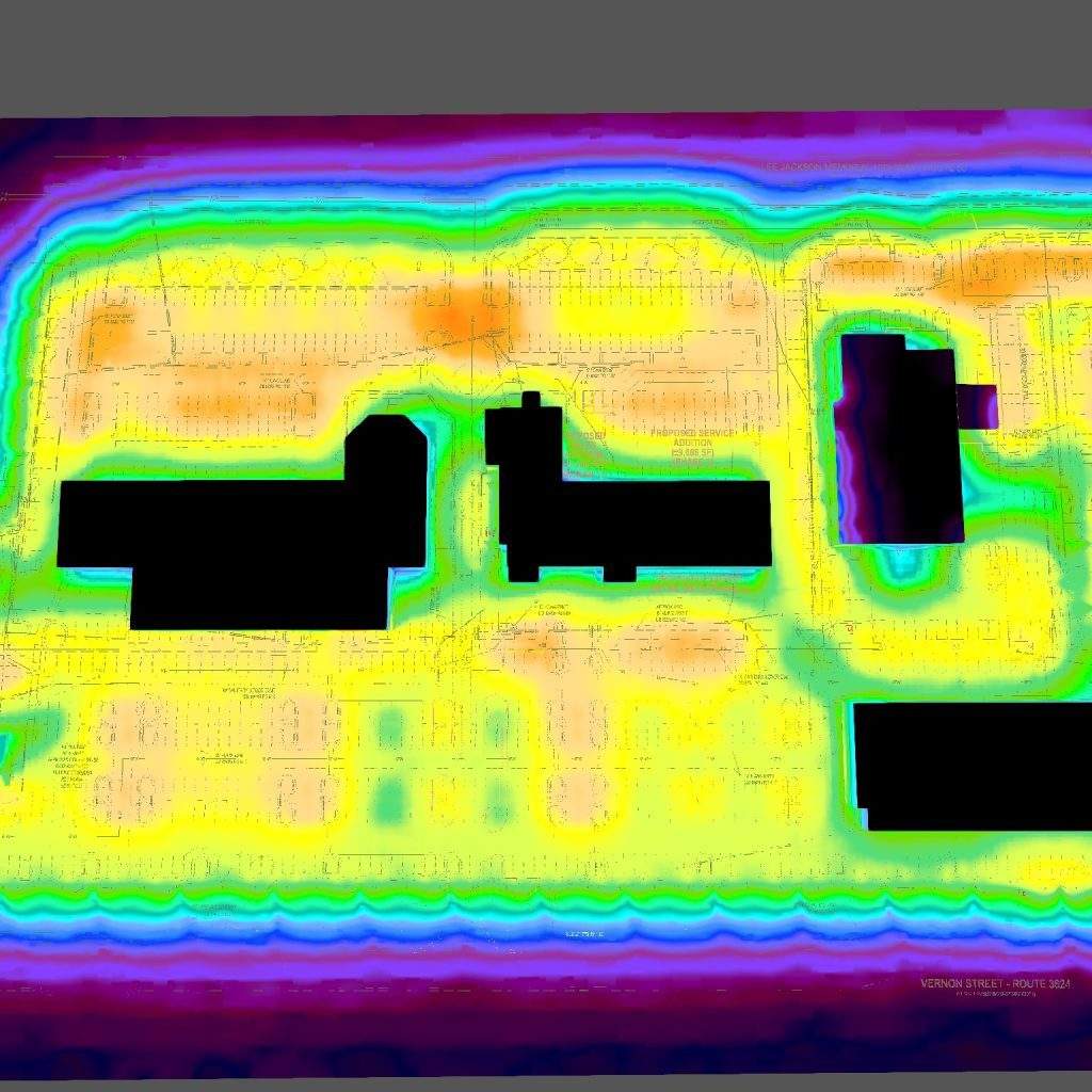
False-color photometric analysis is commonly used to evaluate light distribution, uniformity, and compliance in parking lot lighting designs.
3. Calculation Points
Calculation points show foot-candle values at specific locations.
Designers typically space these points 10–20 feet apart based on project requirements.

In addition to false-color and isoline views, photometric plans also include detailed calculation point grids.
These grids show individual foot-candle values at each calculation point and are used to verify minimum, average, and maximum illuminance levels. Inspectors and engineers rely on these values to confirm compliance with lighting standards and project requirements.
4. Calculation Surface
The calculation surface summarizes performance data for each zone, including:
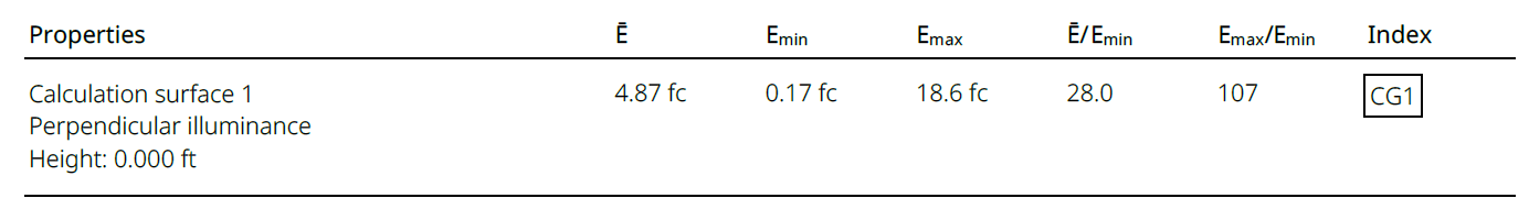
- Ē – average Fc rating (the most important rating for the whole project)
- Emin – maximum value in the calculation surface
- Ē/Emin – uniformity of the light – average/minimum ratios
- Emax/Emin – uniformity of the light – maximum and minimum
The maximum/minimum ratio indicates the overall distribution of lighting, with lower ratios indicating more uniform distribution and increased visual comfort. The average/minimum ratio shows how the least bright point differs from the average rating.
When a Photometric Plan Is Required for Approval
Designers require a photometric plan to verify lighting performance before installation.
Common applications include:
- Parking lots and site lighting
- Warehouses and industrial buildings
- Sports fields and recreational areas
- Car washes and gas stations
- Large commercial interiors
Without a photometric plan, reviewers often delay, reject, or require late redesigns of projects.
Why the Photometric Plan is Important
Photometric plans serve several critical purposes:
- Ensure required light levels are met
- Improve safety and visibility
- Reduce energy waste and over-lighting
- Support permitting and inspections
They also help clients avoid costly revisions after installation.
You can find some real-world case studies for the parking lot photometric plans in the following link.
How Long Does It Take to Create a Photometric Plan?
The time required depends on:
- Project size
- Number of fixtures
- Complexity of the layout
Small projects may take a few hours.
Large or complex projects may take several days.
At Stetra Lighting, we typically deliver a professional photometric plan within 1 to 3 business days.
For quick measurement of the lumens required of a particular space, feel free to use our lumen calculator.
Final Thoughts
A photometric plan is a critical tool for designing safe, efficient, and code-compliant lighting systems.
Whether for a parking lot, warehouse, sports field, or commercial site, a properly prepared photometric plan ensures predictable performance and smoother approvals.
If you are planning a new lighting project or upgrading an existing one, you can order a professional photometric plan directly through Stetra Lighting.
If you like to upgrade or build from the start your sports terrain, parking lot, warehouse, or any other space with new lighting, you can order your photometric report by clicking the button and filling out the form.
Ready to optimize your lighting project with precision and efficiency? Click the button below to get started!
Order Your Photometric Plan👉 Want to see how our lighting solutions work in real-world projects? Explore our detailed case studies showcasing successful designs and their impact.
👉 Want to ensure your outdoor lighting meets the right standards? Check out our comprehensive guide: Foot-Candle Levels for Outdoor Lighting.
Pingback: 11 Best Practices for Contractors Working In Warehouses | LEDLightingSupply.com