A foot-candle (fc) is the standard unit of illuminance used in the United States. It measures the amount of light reaching a specific surface. For architects, engineers, and property owners, foot-candles translate a lighting design concept into a measurable, verifiable outcome. It answers the fundamental question: “How bright will this space actually be?”
This guide explains what a foot-candle is, why it is critical for design and compliance, and how it is used in professional photometric plans.
The Role of Foot-Candles in Lighting Design
The foot-candle is the common language for specifying and verifying light levels. While a fixture’s output is measured in lumens, lumens alone do not describe the brightness of a space. Foot-candles measure the result of the lighting system—how many lumens land on a floor, desk, or parking lot surface.
This metric connects the luminaire’s photometric data (IES file) to the real-world performance of a lighting layout.
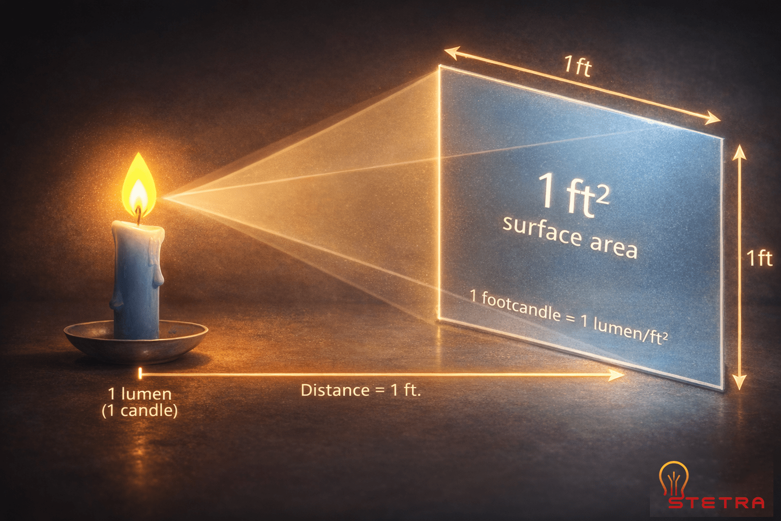
Defining the Unit
The definition is direct: one foot-candle equals one lumen of light distributed uniformly over a one-square-foot area. This relationship between luminous flux (lumens) and area (square feet) makes it a practical tool for design.
The term originated from the light produced by a standard candle at a one-foot distance, an intuitive concept that helps designers visualize illuminance. For more on the history, see the IES’s overview of origins and early lighting standards.
Why This Metric Is Essential
Lighting professionals use foot-candles to answer critical design and safety questions:
- Is the space safe? Meeting minimum foot-candle targets is mandatory for code compliance and reducing liability in walkways, industrial areas, and parking lots.
- Is it functional? Proper illuminance ensures occupants can perform visual tasks efficiently, from reading documents in an office to operating machinery in a warehouse.
- Does it meet code? Building codes and standards from the Illuminating Engineering Society (IES) specify required foot-candle levels that projects must meet to obtain permits.
Foot-candles provide the data needed to prove a design works. They document performance, ensure compliance, and deliver a space that meets owner expectations for safety and visual comfort.
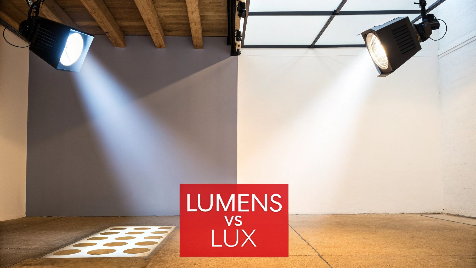
Connecting Foot-Candles, Lumens, and Lux
Understanding the difference between foot-candles and lumens is fundamental. Lumens measure the total light output from a source. A foot-candle measures illuminance—the density of light arriving at a surface.
The conversion from a fixture’s lumen output to the foot-candle level on a work plane depends on two key factors: distance and light distribution (optics).
The Role of Distance and Optics
The inverse-square law dictates that illuminance decreases significantly with distance. As the distance from a light source doubles, the light level drops to approximately one-quarter of its initial value. A fixture mounted at 20 feet will deliver far fewer foot-candles than the same fixture at 10 feet.
Fixture optics, or beam angles, control how lumens are distributed. A 10,000-lumen floodlight with a wide distribution and a 10,000-lumen spotlight with a narrow beam produce entirely different foot-candle readings on the ground. Relying on lumen output alone is a common and costly design error.
Converting Between Foot-Candles and Lux
On international projects, the metric unit for illuminance is lux. The conversion is simple:
- One foot-candle = one lumen per square foot.
- One lux = one lumen per square meter.
The standard conversion is 1 foot-candle ≈ 10.76 lux. A target of 30 fc is equivalent to approximately 323 lux. For a detailed analysis, see our guide on foot-candles vs. lux.
Foot-candles provide a practical basis for lighting design. They quantify the light that actually matters—the light arriving at the task surface.
Recommended Foot-Candle Levels by Application
A successful lighting design begins with establishing appropriate light level targets. These targets, measured in foot-candles, ensure a space is safe, functional, and compliant. The Illuminating Engineering Society (IES) provides widely adopted recommendations for various applications.
IES guidelines are based on research into visual performance, safety, and occupant comfort. For example, a parking lot may only require 1–5 fc for safe navigation, while an office requires 30–50 fc on desktops to prevent eye strain.
Initial vs. Maintained Foot-Candles
A critical distinction in professional design is between initial and maintained foot-candles.
- Initial foot-candles describe light levels on day one, with new, clean fixtures.
- Maintained foot-candles account for light loss over time due to factors like lumen depreciation and dirt accumulation (Light Loss Factor, or LLF).
Professional designs must target maintained foot-candle levels. Designing for initial levels is a common mistake that leads to underlit, non-compliant spaces within a few years.
Setting Practical Targets
The specified foot-candle target directly influences fixture selection, spacing, and mounting height. Higher targets typically require more powerful fixtures or closer spacing, impacting both initial cost and long-term energy consumption.
The following table summarizes common maintained foot-candle targets based on IES recommendations.
Typical Maintained Foot-Candle (fc) Targets by Space
| Application Type | Target Foot-Candle Range (fc) | Key Design Considerations |
|---|---|---|
| Commercial Office | 30–50 fc | Measured on work plane; focus on glare control and visual comfort. |
| Retail Store | 50–75 fc | Higher general levels with accent lighting to highlight merchandise. |
| Warehouse (Storage) | 10–20 fc | General visibility in aisles; vertical illuminance on racks is important. |
| Warehouse (Picking) | 30–50 fc | Higher levels required for task accuracy in active work zones. |
| Parking Garage | 5–10 fc | High uniformity is critical to eliminate shadows and enhance safety. |
| Parking Lot | 1–5 fc | Focused on safe navigation; light trespass and BUG ratings are key. |
| Classroom | 30–50 fc | Uniform, low-glare illumination for reading and visual tasks. |
Explore more detailed targets in our guide to foot-candle requirements by area. Using IES standards provides a defensible baseline for developing a photometric plan that meets code and owner requirements.
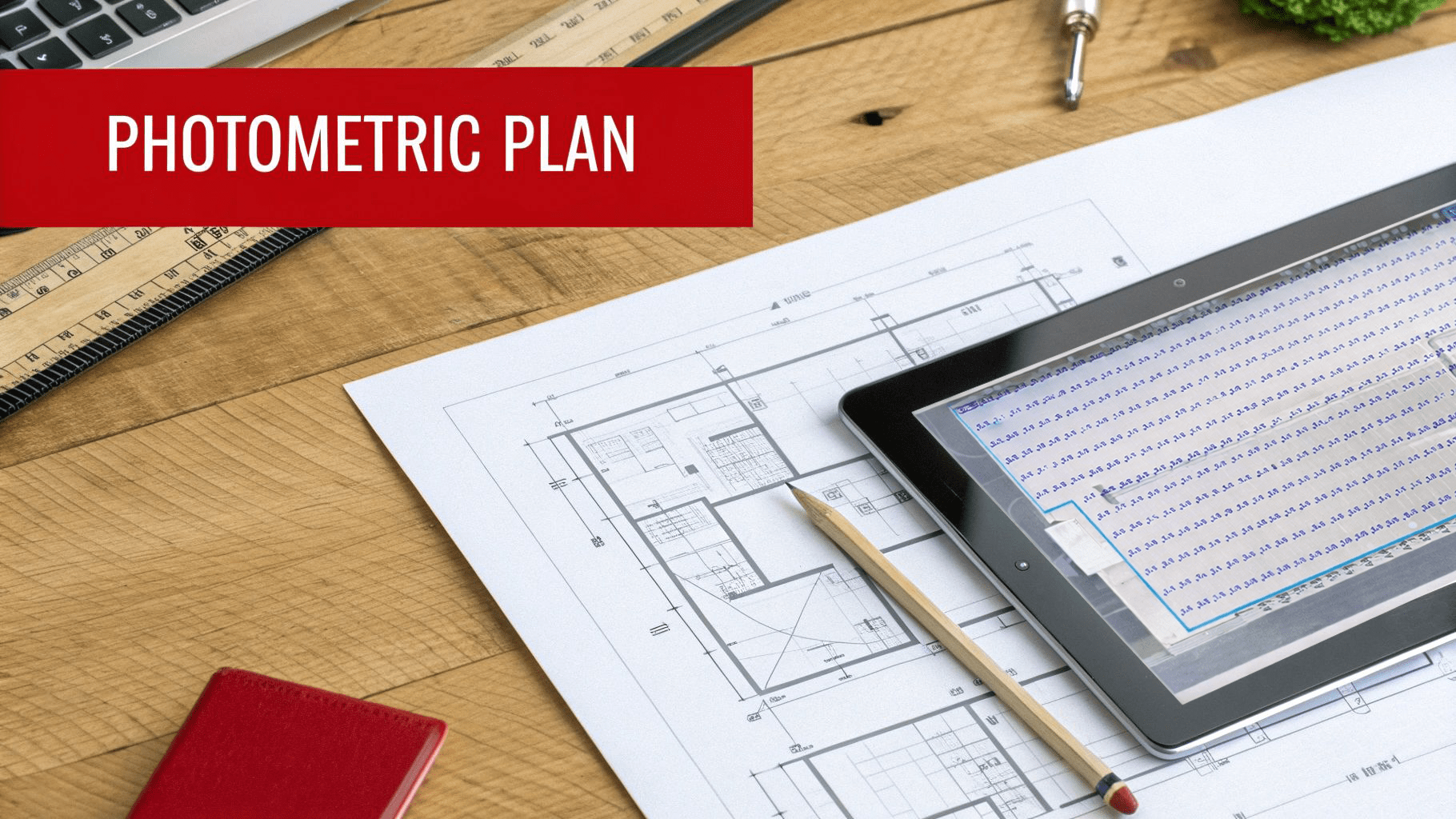
Using Foot-Candles in Photometric Plans
A photometric plan is the primary tool for translating foot-candle targets into a buildable lighting layout. It provides a visual and numerical analysis of how light will be distributed across a site, ensuring the design meets specified illuminance and uniformity criteria before installation.
These plans are essential for architects, engineers, and permitting authorities to verify compliance with safety standards and local lighting ordinances. When a project requires documented proof of performance, Stetra Lighting provides a permit-ready photometric plan to ensure code compliance and approval.
Key Metrics on a Photometric Plan
A photometric plan presents several key metrics to evaluate a design’s effectiveness:
- Average Foot-Candles: The overall illuminance level across the calculation area.
- Minimum and Maximum Foot-Candles: These values identify the darkest and brightest points, which are critical for assessing safety and visual comfort.
- Uniformity Ratios: Ratios such as average-to-minimum or maximum-to-minimum quantify the evenness of the light distribution.
Low uniformity ratios are desirable, as they indicate consistent illumination without harsh hot spots or dark shadows. For instance, a specification may require a 30 fc average with a maximum 4:1 average-to-minimum uniformity ratio to ensure visibility throughout a space.
Where Compliance Meets Practicality
The use of foot-candles in American building codes is well-established. Early IES standards from the 1920s required 15 fc for factory work, a number that grew with technological advancements. More information on the historical development of lighting standards is available.
Today, photometric plans are a standard requirement for permitting most commercial projects. They provide documented evidence that a design meets all applicable safety and energy codes.
How to Measure Foot-Candles On-Site
On-site verification with a calibrated light meter is the final step to confirm a lighting installation meets the design intent. This process provides physical measurements of foot-candle levels, bridging the gap between digital simulation and real-world performance.
Field measurements validate that the performance targets documented in the photometric plan were achieved.
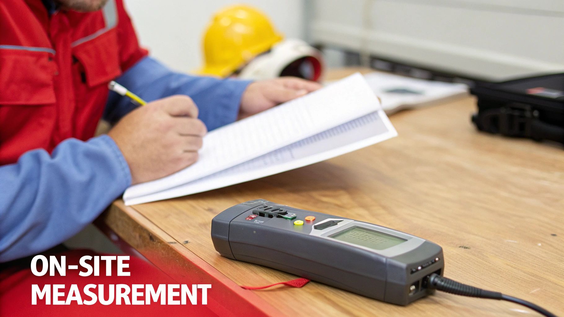
The Standard Measurement Procedure
To ensure accuracy, the light meter’s sensor is placed on the specified task surface (e.g., floor, desk) at the height defined in the photometric plan. The person taking the reading must not cast a shadow over the sensor, as this will result in an artificially low measurement.
Multiple readings should be taken at grid points corresponding to the calculation grid in the original plan. These points are then averaged to assess overall performance.
Comparing Field Data to the Design
The collected field data is compared directly to the values from the photometric plan. This comparison validates that average, minimum, and uniformity targets have been met.
Significant discrepancies between the plan and field measurements can indicate installation errors. Common issues include incorrect mounting heights, improper fixture aiming, or surface finishes that differ from what was specified in the design model.
Identifying these issues allows for corrections before project closeout. For more information, see this overview of essential lighting design tools.
Common Design Mistakes to Avoid
Effective lighting design requires avoiding common pitfalls that lead to poor performance and non-compliance. The most prevalent error is relying on outdated rules of thumb instead of a detailed photometric analysis.
Focusing solely on average foot-candles while ignoring uniformity is another frequent mistake. This oversight creates environments with distracting hot spots and unsafe dark areas. To achieve balanced illumination, understanding why the lighting uniformity ratio is crucial is essential.
Forgetting Future Performance
Designing for initial (day-one) performance is a critical error. All lighting systems degrade over time due to dirt accumulation and LED lumen depreciation. Failing to apply a Light Loss Factor (LLF) in calculations will result in an underlit space years before its intended service life ends.
Inaccurate Calculation Methods
Using generic “lumens per square foot” calculations is unreliable. This oversimplified method ignores the critical factors that determine final light levels:
- Fixture Optics: The shape and direction of the light distribution.
- Mounting Height: The distance from the fixture to the task plane.
- Beam Angles: The concentration or spread of the light.
The only reliable method is to establish clear foot-candle and uniformity targets, select fixtures with appropriate optics, and execute a professional photometric analysis. This process guarantees predictable, compliant results for any project requiring permitting or adherence to strict performance criteria.