Effective exterior lighting for buildings achieves three primary goals: enhancing architecture, ensuring safety, and meeting energy codes. A professional design is a technical exercise in balancing visual appeal with functional performance. This approach prevents common issues like glare, light trespass, and energy waste.
Defining the Goals of Exterior Building Lighting
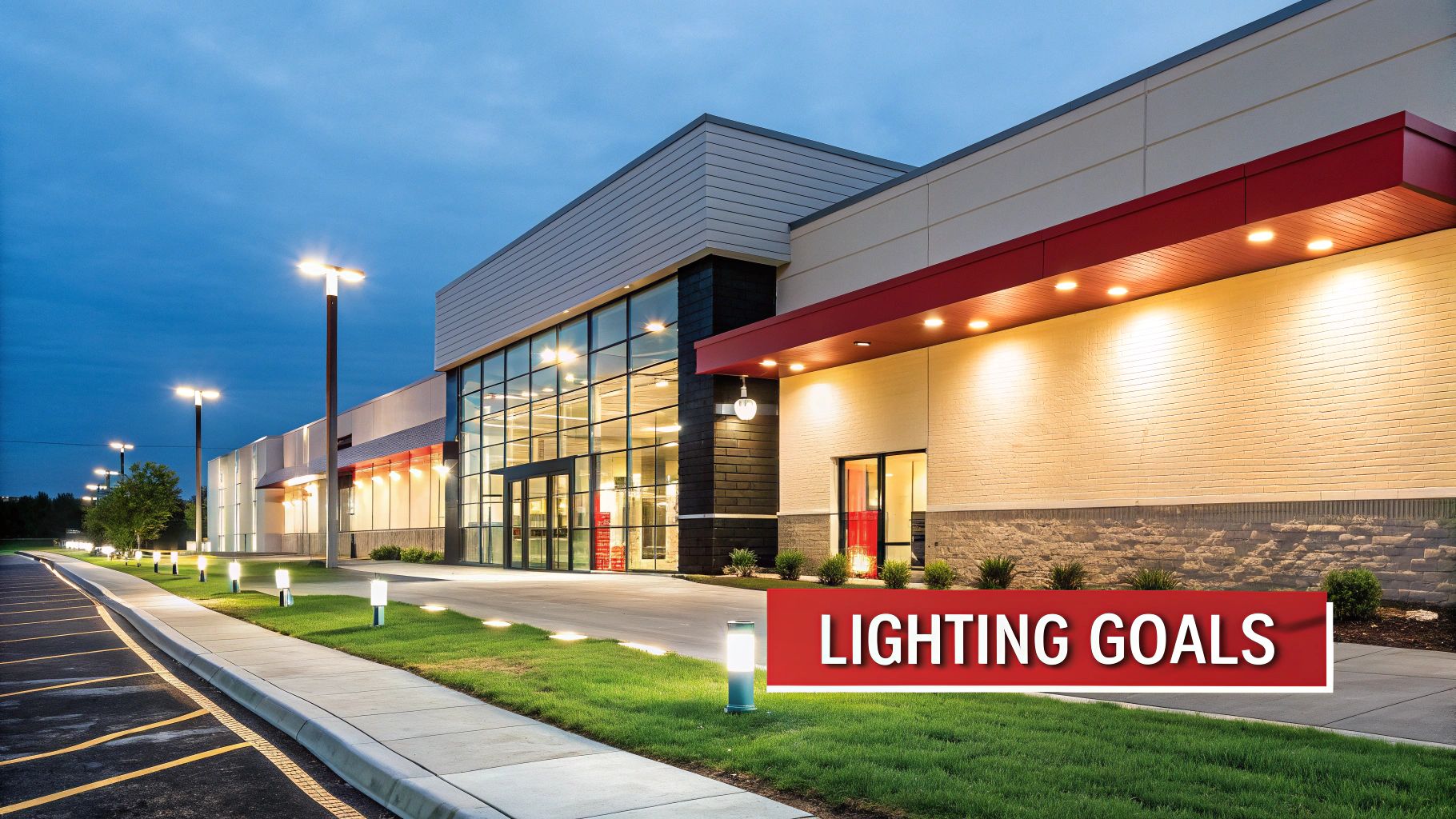
Exterior lighting is an integral part of building design, serving distinct purposes that add value, security, and compliance. Architects, engineers, and property owners must establish clear objectives to develop a cohesive and efficient lighting scheme.
Every exterior lighting project is guided by three core objectives:
- Aesthetics and Architecture: Lighting should highlight a building’s key features, create visual interest, and reinforce brand identity. Thoughtful illumination transforms a building’s appearance after dark. Effective strategies are covered in our guide to facade lighting techniques.
- Safety and Security: Proper illumination of pathways, entrances, and parking areas is critical. It ensures safe navigation for pedestrians and vehicles and acts as a deterrent to unauthorized activity.
- Compliance and Efficiency: All projects must adhere to local energy codes, dark-sky ordinances, and lighting power density (LPD) requirements. Meeting these regulations minimizes environmental impact and reduces operating costs.
Establishing Light Levels and Performance Metrics
Exterior lighting design relies on quantitative data to ensure safety, efficacy, and compliance. Professional projects begin by establishing targets for light levels (illuminance, measured in foot-candles) and distribution (uniformity). These targets are based on recommendations from the Illuminating Engineering Society (IES).
A design must achieve specific foot-candle (fc) levels for different zones. For example, building entrances require higher illuminance than general walkways for safety and security. The uniformity ratio is equally critical, as it defines how evenly light is distributed across a surface. Proper uniformity prevents dark spots and harsh contrasts that can compromise safety. For specific values, consult our guide to outdoor lighting foot-candle requirements.
IES Recommended Minimum Light Levels
The IES provides foundational standards for lighting design, offering foot-candle targets that ensure functionality and safety. These recommendations are the basis for a professional photometric plan.
| Application Area | Average Maintained Foot-candles (fc) | Uniformity Ratio (Avg:Min) |
|---|---|---|
| Building Entrances | 5.0 fc | 4:1 |
| Parking Lots (General) | 1.0 fc | 4:1 |
| Pedestrian Walkways | 0.5 fc | 4:1 |
| Building Facades | 2.0 – 15.0 fc | Varies by design |
Adherence to these guidelines is the first step toward a lighting plan that meets the technical requirements of local codes and safety standards.
Qualitative and Efficiency Metrics
The quality of light also impacts the user experience. Metrics like Color Temperature (CCT) and Color Rendering Index (CRI) are important. CCT, measured in Kelvin (K), determines the perceived warmth or coolness of the light. A high CRI ensures building materials and colors are rendered accurately.
Energy efficiency is mandatory. Energy codes like ASHRAE 90.1 enforce strict Lighting Power Density (LPD) limits. Adhering to LPD, measured in watts per square foot, is non-negotiable for permit approval. It prevents energy waste by capping the total power a lighting system can consume.
Verifying all metrics before installation is essential. This is accomplished with a photometric plan, which provides the necessary calculations to prove the design meets IES recommendations and local energy codes. For projects requiring municipal approval, you can order a photometric plan to supply the documentation needed for a streamlined permitting process.
The Critical Role of Photometric Planning
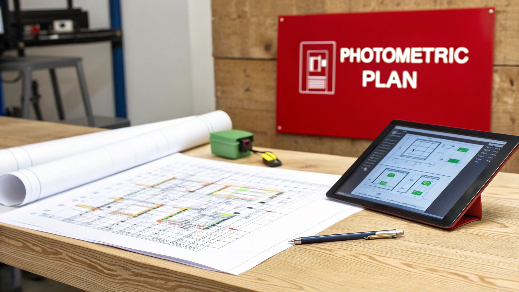
A photometric plan is the technical blueprint for an exterior lighting design. This detailed simulation models how the proposed system will perform, preventing costly mistakes and ensuring project goals are met.
The plan is a visual map of light distribution. It uses luminaire locations, fixture data from IES files, and calculation grids to generate a precise model. The analysis provides quantitative results, including foot-candle levels and uniformity ratios across the site.
Verifying Compliance Before Construction
Designing exterior lighting without photometric analysis introduces significant risk. It can lead to incorrect fixture spacing, improper optics, or inadequate light levels, resulting in performance failures and code violations.
For projects requiring municipal review, a photometric plan is mandatory. It provides the verifiable data needed to satisfy local lighting ordinances and energy codes. A robust photometric plan validates that the lighting system achieves its safety, security, and aesthetic goals while remaining within regulatory limits.
Stetra Lighting produces permit-ready photometric plans engineered to meet technical requirements before submittal. This documentation demonstrates due diligence and reduces the risk of costly revisions and project delays. For more information, our article explains what a photometric plan includes.
Fixture Selection, Optics, and Placement
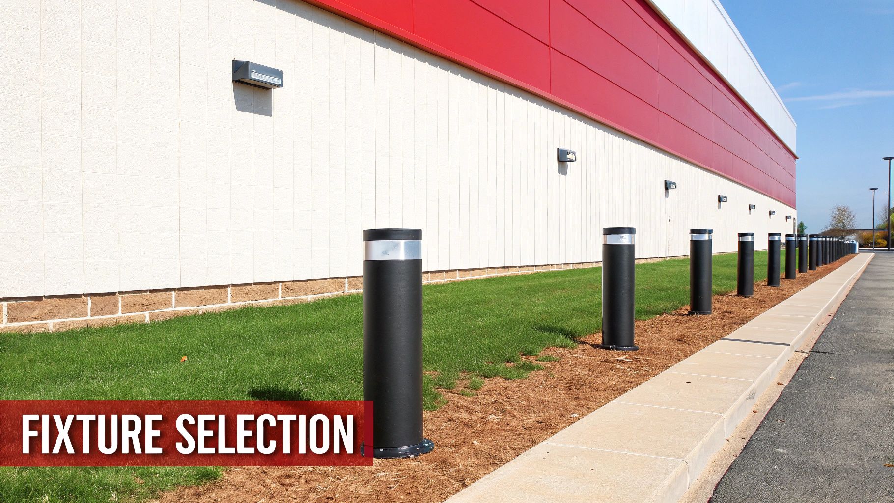
The success of exterior lighting for buildings depends on selecting the correct fixture and optical system for each application. Lumen output is secondary to the precise control of light distribution.
Common exterior fixtures each have a specific function. Wall packs provide general security lighting along perimeters. Floodlights are used for broad illumination of parking areas or architectural features. Bollards define walkways and landscape edges, while in-ground uplights create accent effects on facades.
Choosing Optics and Light Distribution
A fixture’s optics—its lens and reflector system—shape the light into a useful pattern, described by a beam angle and an IES light distribution type. These factors are more critical than lumen output because they determine how light covers a surface.
IES distribution types classify how far forward a fixture distributes light, which is critical for area lighting:
- Type I: A long, narrow pattern for single-lane paths.
- Type II: A wider pattern for two-lane roads or broader pedestrian areas.
- Type III: Throws light further forward, suitable for parking lot perimeters.
- Type IV: Pushes most light forward in a “forward throw” pattern, often used on wall-mounted fixtures.
- Type V: A symmetrical, circular pattern for intersections or large open areas.

Selecting the correct IES distribution maximizes efficiency and reduces light waste. A photometric analysis verifies this selection before equipment is ordered.
Proper placement is determined by mounting height and spacing criteria. Following these guidelines achieves uniform light levels without creating dark spots or wasteful overlaps. A well-designed system meets target foot-candle levels with the minimum number of fixtures required.
Controlling Glare and Light Trespass
Effective exterior lighting for buildings must control where light is directed. Glare and light trespass are two significant issues that result from poor lighting design. These problems create visual discomfort, safety hazards, and can violate local ordinances.
Glare is excessive brightness from an unshielded or poorly aimed fixture. Light trespass is stray light that spills beyond the property line, illuminating adjacent properties.
The IES BUG Rating System
The Illuminating Engineering Society (IES) developed the BUG rating system to standardize luminaire performance regarding light pollution. The rating measures light output in three critical zones:
- Backlight (B): Light directed behind a fixture, the primary cause of light trespass.
- Uplight (U): Light directed above the horizontal plane of the fixture, which contributes to sky glow.
- Glare (G): High-angle forward light that causes visual discomfort for drivers and pedestrians.
Each component (B, U, and G) is assigned a rating from 0 (best) to 5 (worst). Local lighting codes often specify maximum BUG ratings. For example, a rural zone may require a B1-U0-G1 rating. Understanding these ratings is essential for compliant design. You can learn more in our guide on the IES BUG rating system.
Understanding IES BUG Ratings
| Rating Component | Description | Best Practice Goal |
|---|---|---|
| Backlight (B) | Measures light directed behind the fixture, which can cause light trespass onto neighboring properties. | B0-B1: Minimal backlight to keep light contained within the target area. |
| Uplight (U) | Measures light directed above the horizontal plane, contributing to sky glow and environmental disruption. | U0: No uplight. This is the standard for dark-sky friendly lighting. |
| Glare (G) | Measures high-angle forward light that causes visual discomfort for pedestrians, drivers, or occupants. | G0-G1: Low glare output to ensure visual comfort and safety. |

A photometric analysis is the only method to verify that a design meets these standards. Stetra Lighting provides photometric services to ensure projects are fully compliant by selecting fixtures with appropriate BUG ratings and optimal aiming.
Practical Mitigation Strategies
Controlling glare and light trespass depends on proper fixture selection and placement.
Full-cutoff fixtures direct all light downward, eliminating uplight and achieving a U0 rating. Accessories such as shields, louvers, and baffles provide additional control to block stray light from affecting sensitive areas.
Proper aiming is also critical. A well-shielded fixture aimed too high will still cause glare. The objective is to illuminate the intended surface without the light source being directly visible from off-site locations.
Integrating Controls for Energy Code Compliance
Modern energy codes, such as ASHRAE 90.1, mandate the use of automated controls for professional exterior lighting for buildings projects. An efficient system must also be intelligent, using light only when and where it is needed. A controls strategy is required for permit approval in most jurisdictions.
Essential Control Strategies
These control methods are fundamental building blocks for code compliance.
- Photocells: A photocell is a dusk-to-dawn sensor that reads ambient light levels. It automatically turns fixtures on at sunset and off at sunrise, preventing energy use during daylight hours.
- Astronomical Timeclocks: These devices track time and geographic location to schedule automatic shutoffs during low-traffic hours, such as from midnight to 6 a.m.
- Motion Sensors: In areas requiring continuous security lighting, motion sensors are used to dim lights by at least 50% when no activity is detected. The lights return to full brightness instantly upon detecting motion, balancing safety with energy savings.
Integrating these controls is a code requirement. A lighting design without a clear control strategy will not pass the permitting process. This requirement reflects a broader industry trend toward intelligent systems, as detailed in our guide on intelligent lighting controls. A photometric plan is critical to demonstrate that both light levels and control functions meet current municipal standards.