

Tennis court lighting pole height depends on the court layout, pole setbacks, selected fixture photometry, aiming and the project criteria. There is no single height that works for every court. A tennis court photometric plan compares these choices before poles and luminaires are purchased. This guide explains the design checks and retains historical diagrams and an indoor project example for context.
Standards for Tennis Lighting
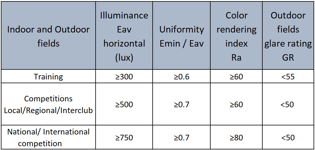
For a U.S. project, identify the sport, level of play, owner requirements and reviewing authority before selecting light-level and uniformity criteria. The IES currently lists ANSI/IES RP-6-24, Lighting Sports and Recreational Areas. Confirm the edition and project-specific requirements with the responsible designer; professional-event and broadcast criteria may require additional review. The legacy European comparison image below is retained as historical context and is not a U.S. design specification. European and U.S. criteria should not be treated as interchangeable.
Planning the lighting poles
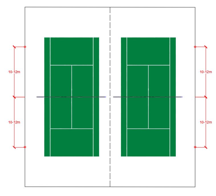
The diagrams below illustrate two- and three-pole arrangements beside a pair of courts. Their dimensions belong to those examples. Pole count and spacing must be tested with the selected IES files, mounting heights, aiming, court boundaries and neighboring-property conditions. Use our sports lighting photometric-plan guide for the broader study workflow.

Tennis court lighting pole height
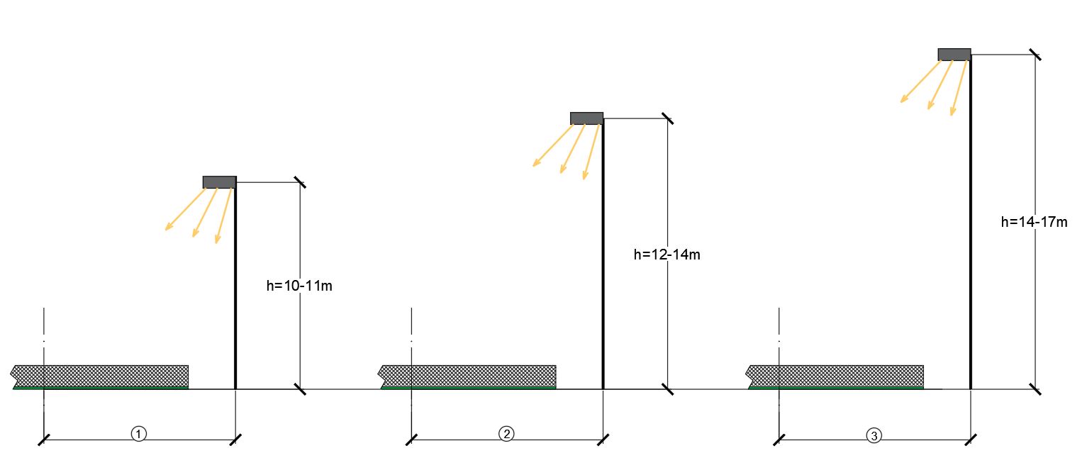
Select pole height together with setback, optical distribution and aiming. Raising or lowering a fixture changes the light distribution and the viewing geometry; neither a taller pole nor a higher-output fixture automatically solves glare. The legacy height diagram illustrates roughly 10–17 m (33–56 ft) for its pictured configurations. Those dimensions are examples, not recommended U.S. minimums or maximums. Compare candidate heights with point-by-point calculations, the specified uniformity metric and glare/spill-light checks.
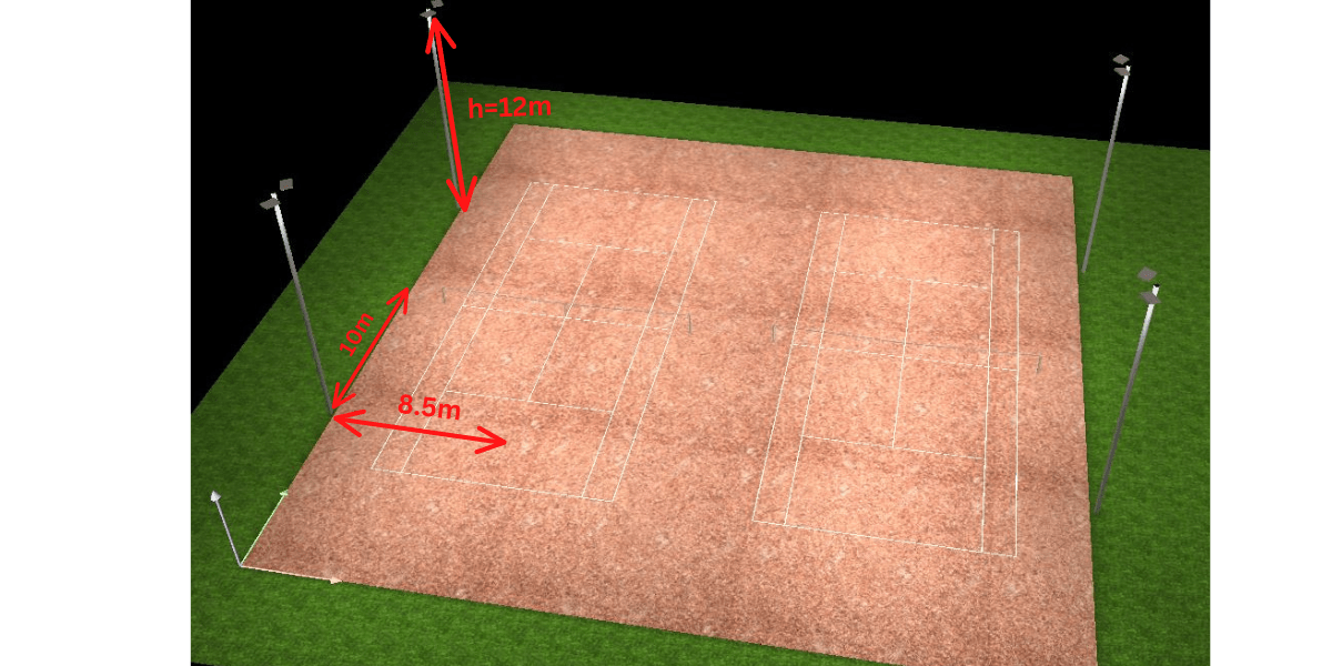
The illustrated layout uses 12 m poles (about 39 ft), with the offsets shown in the original diagram. Keep those dimensions attached to this example; the appropriate layout for a different site depends on its actual geometry and criteria.
Lighting for Indoor Tennis
Indoor tennis lighting must account for court run-off areas, ceiling or structural geometry, surface reflectance, mounting restrictions and the player’s view of a moving ball. The illustrated arrangements show possible direct and indirect approaches; they do not establish a single mounting method for every building.

Review the bright source from normal player positions, including the upward view during serves and lobs. Optics, shielding, fixture position and aiming should be assessed together. Asymmetric distributions can help control where light goes, but they do not guarantee a glare-free court. Our glare guide explains the distinction between discomfort and reduced visibility.
Choosing luminaires for tennis court lighting
Choose luminaires from verified photometry for the intended model, optic and output configuration. Check mounting, aiming, controls and maintenance assumptions alongside the electrical load. Fixture wattage or efficacy alone cannot show the illuminance, uniformity or glare outcome on a court. Avoid specifying a universal wattage range before calculating the layout.
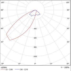
Test the actual symmetrical or asymmetrical distribution in the model. An optic that performs well at one setback or tilt can create excessive light outside the playing area in another arrangement. Confirm ball visibility, player sight lines and property-boundary effects rather than choosing a beam angle from a generic rule.
What a Tennis Court Photometric Report Should Include
Prepare the photometric study before finalizing pole locations and fixture purchases. It should identify the selected photometry, mounting and aiming, calculation surfaces, grid, light-loss assumptions and project criteria. Include the light-level and uniformity summaries and any required glare or boundary evaluation. For the review sequence, see how to read a photometric plan.
Use lighting-calculation software to model the selected fixture data and project geometry. The report should identify its inputs, calculation surfaces and assumptions so another project team member can understand the results and compare a revision on the same basis.
Photometric grid
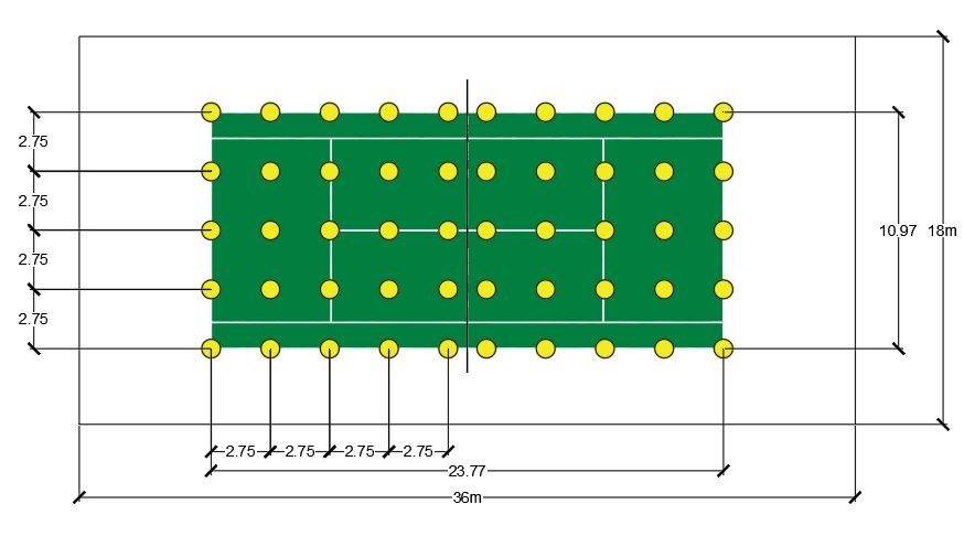
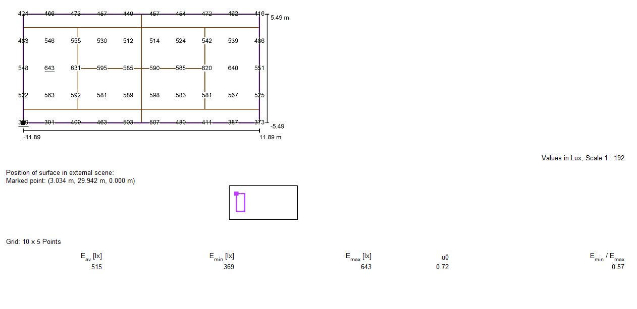
The calculation grid must cover the playing and surrounding areas required by the adopted criteria, at the stated plane height and spacing. The pictured grid is an illustration. Define any separate horizontal or vertical checks explicitly so reports can be compared on the same basis.
Checks outside the playing area
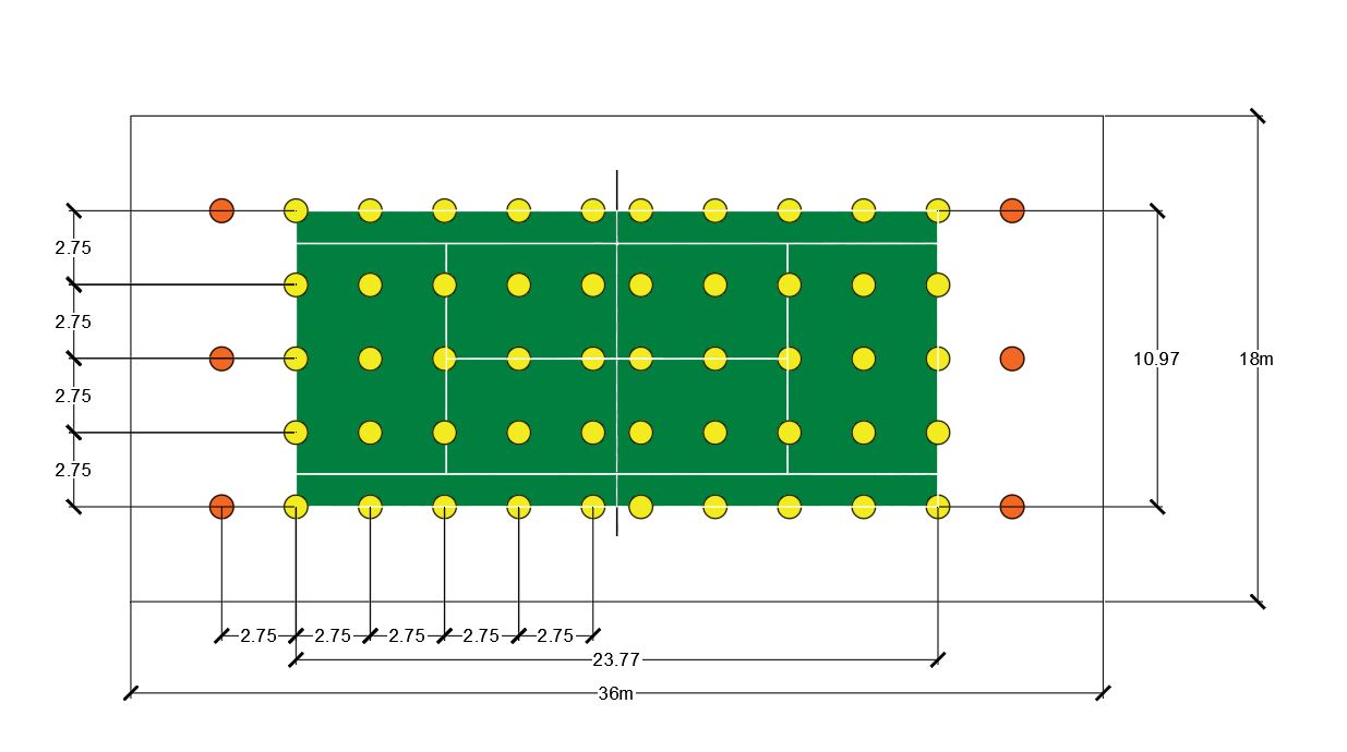
The orange points in the illustration show an additional edge-comparison check used in this example. Apply such a percentage check only when the project’s identified criteria require it. State the reference points, calculation plane and comparison method; the pictured 80% relationship is not a universal rule for all U.S. tennis courts.

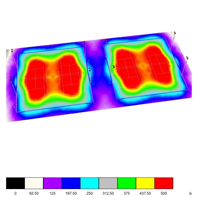
False-color views and calculation results
Glare calculation and observer positions
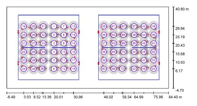
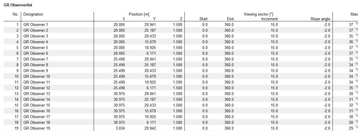
Indoor Tennis Hall: Project Example
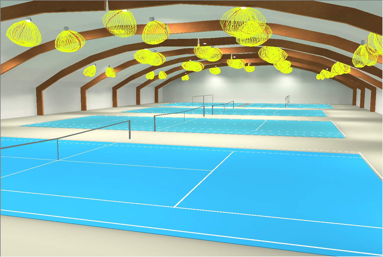
This indoor example shows four courts and the original metal-halide lighting arrangement. The original design lists 20 lamps rated at 400 W per court: 80 × 400 W = 32 kW of rated lamp power, before ballast losses. The photos and layout drawings show the fixture locations and roof geometry. For an energy comparison, use system input power and the actual operating conditions, not lamp wattage alone.
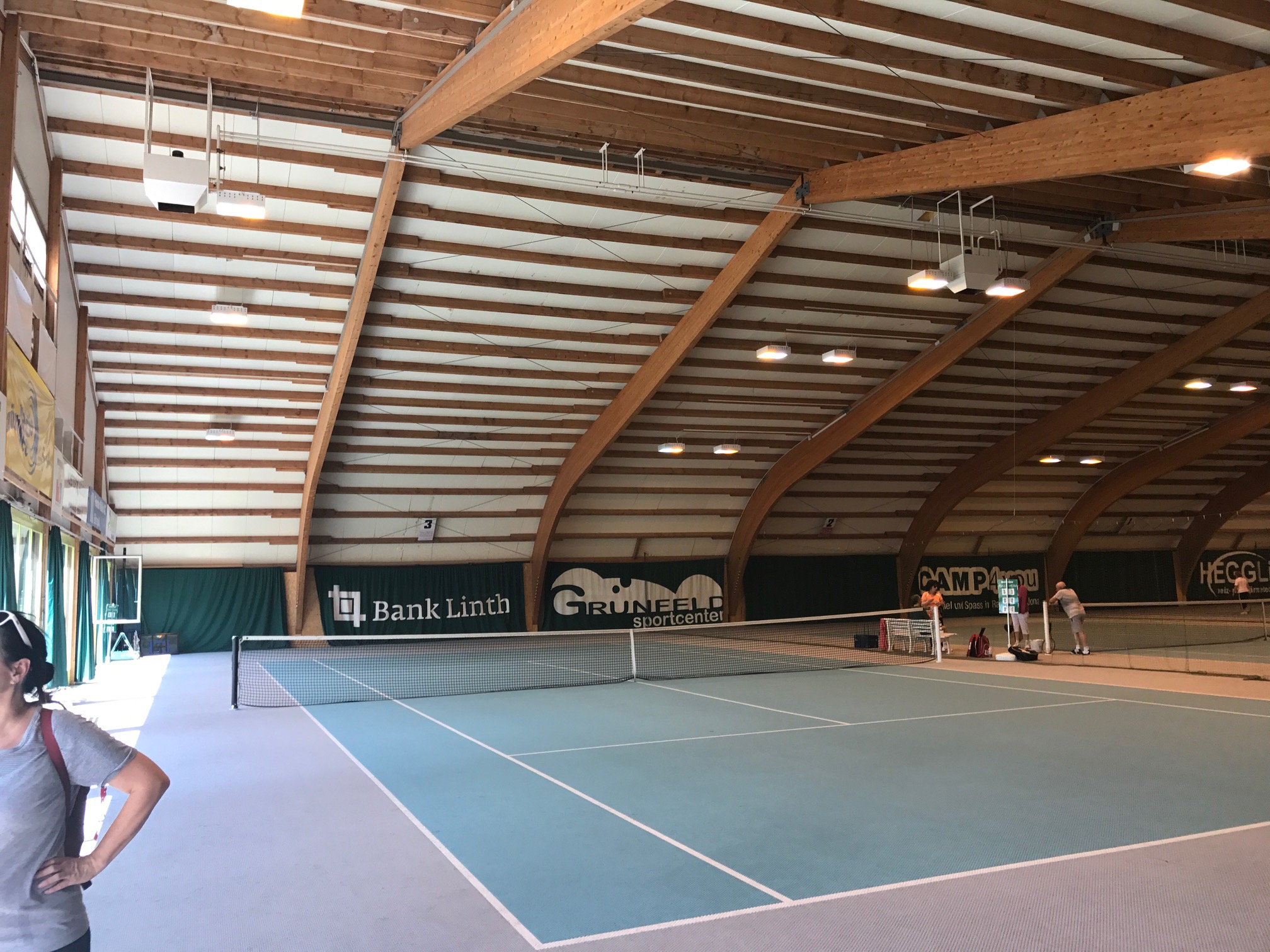
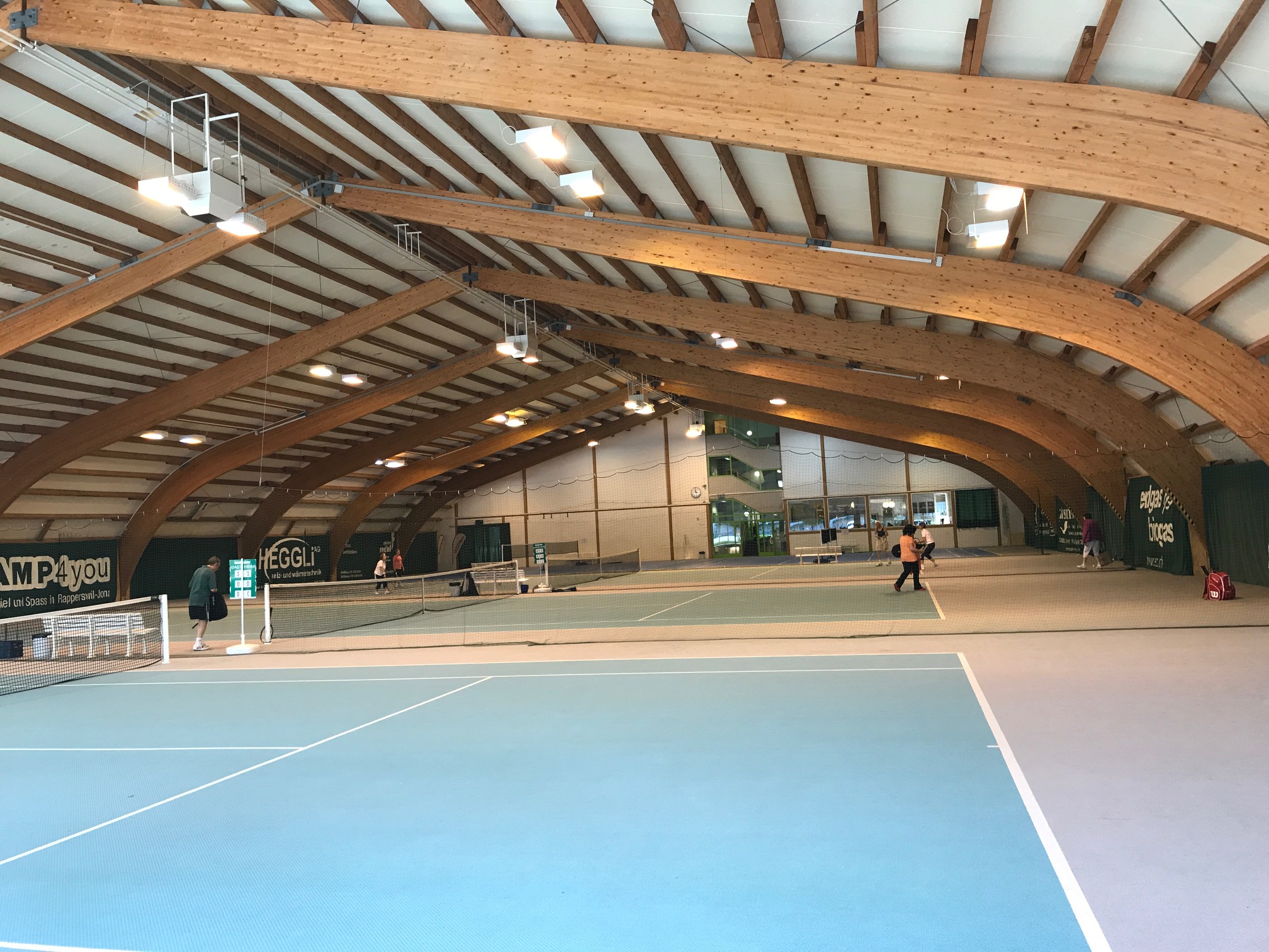

The LED comparison in this example lists 16 kW. Compared with the original 32 kW lamp-power figure, that is a 50% reduction in the stated wattage figures. It is not a measured electricity-bill result: operating hours, controls and ballast/driver losses also affect energy use. Check the complete fixture schedules and calculation assumptions when assessing a retrofit.

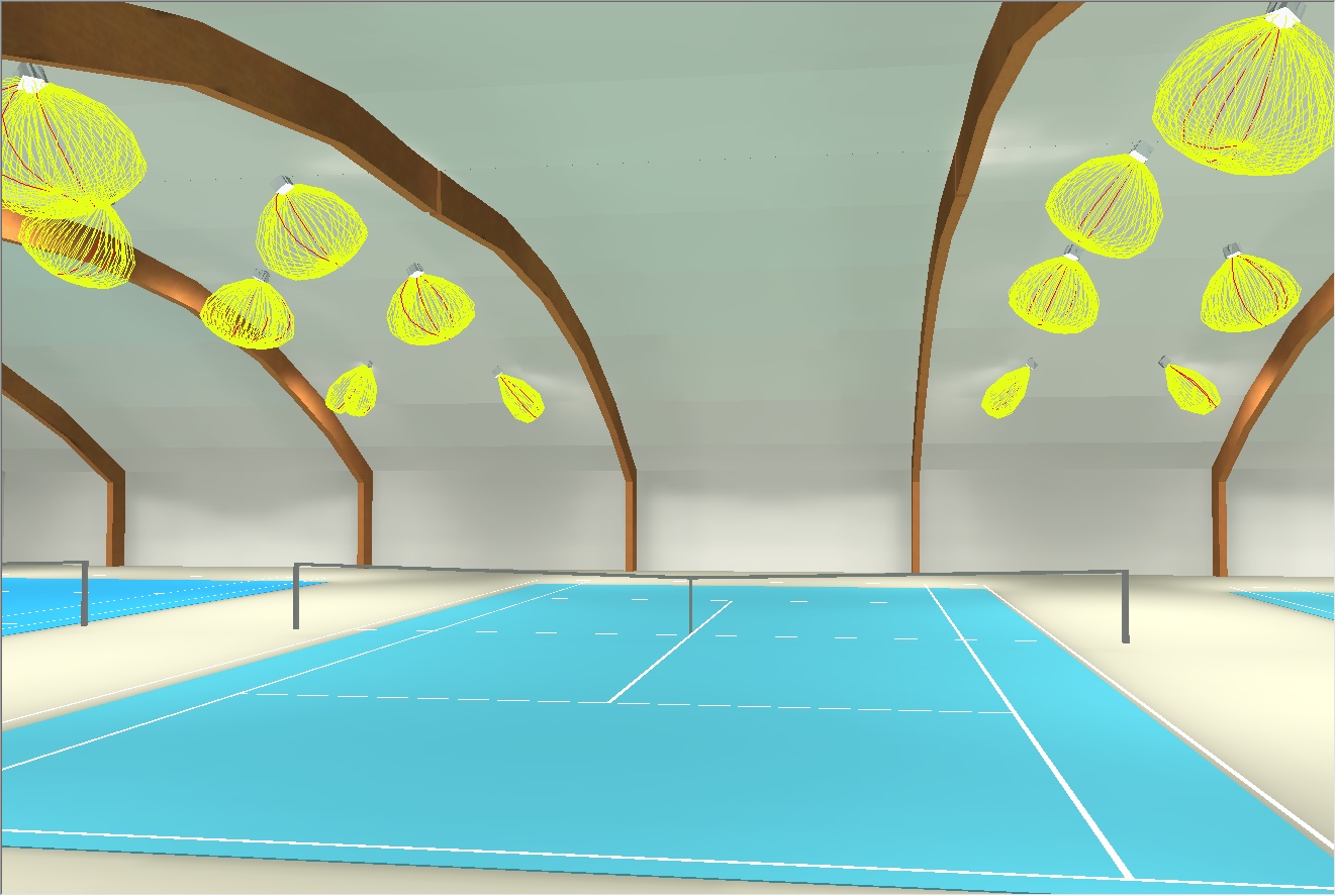
The following 3D views illustrate fixture positions and the court layout within the roof geometry. Use them for coordination and orientation; compare the numerical calculation output when checking the project criteria.
Results from the photometric report with the new lighting setup

The example report shows calculated values in lux on a horizontal surface identified as 1 m above the floor. That is the reported surface for this example, not a universal U.S. tennis calculation height. Read the numerical summary and its exact uniformity formula together. For example, Min/Avg = 0.70 corresponds to Avg/Min ≈ 1.43:1; Avg/Min cannot equal 0.70 for nonnegative illuminance values with a positive minimum. Our uniformity-ratio guide explains the calculation.
Conclusion
Stetra Lighting has more than 10 years of experience preparing photometric plans. Send the court layout, project location, proposed pole limits, fixture data and review criteria so we can confirm the study scope. Use Request a Photometric Plan for a project-specific quotation, or review what affects photometric-plan cost first.