Dark sky compliant lighting is a technical approach to outdoor illumination that mitigates light pollution. The design objective is to direct light only where needed, using appropriate color temperatures. This requires fully shielded fixtures with a U0 BUG rating, which eliminates uplight, reduces energy consumption, and preserves the night sky.
Fundamentals of Dark Sky Compliance
Designing for dark sky compliance is a technical discipline governed by measurable standards. For architects, engineers, and contractors, understanding these fundamentals is critical for lighting compliance and permitting.
The objective is to illuminate a space for safety and function without contributing to skyglow, light trespass, or glare.
This is achieved by adhering to five key principles of responsible outdoor lighting. Each principle addresses a specific aspect of light production and distribution.
Core Principles of Compliant Design
-
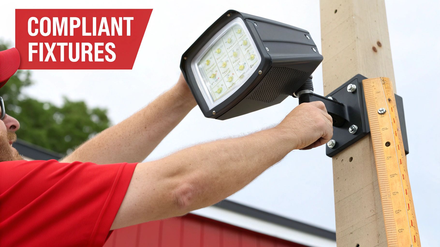
Specify Fully Shielded Fixtures: This is a mandatory requirement. All light must be directed downward. The industry standard is the BUG rating (Backlight, Uplight, Glare). A U0 rating is mandatory, indicating zero uplight escapes the fixture.
-
Prevent Over-lighting: Use only the minimum light levels required for the specified task. Specify appropriate lumen packages and verify performance with a photometric plan to ensure foot-candle targets are met but not exceeded.
-
Select Warmer Color Temperatures: Correlated Color Temperature (CCT) is a critical factor. Cool-white light (4000K and above) contains high levels of blue-spectrum light that scatters in the atmosphere, increasing skyglow. Compliant designs typically require a CCT of 3000K or lower.
-
Apply Light with Precision: Utilize correct optics and fixture placement to illuminate the target area exclusively. This prevents light trespass onto adjacent properties and sensitive environmental zones.
-
Integrate Adaptive Controls: Use timers, dimmers, and motion sensors to ensure light is active only when necessary. This practice reduces energy costs and minimizes the impact of artificial light.
Why Technical Standards Matter
Adherence to lighting standards has significant impacts. In the United States, outdoor lighting for streets and parking facilities consumes an estimated 120 terawatt-hours of energy annually. Approximately 30% of this light is wasted as uplight. This waste costs $3.3 billion and generates 21 million tons of CO2 emissions per year.
A compliant design requires a documented process proving every luminaire—its placement, output, and controls—functions as a system to meet strict performance criteria. It is not achieved by selecting fixtures labeled “dark sky friendly.”
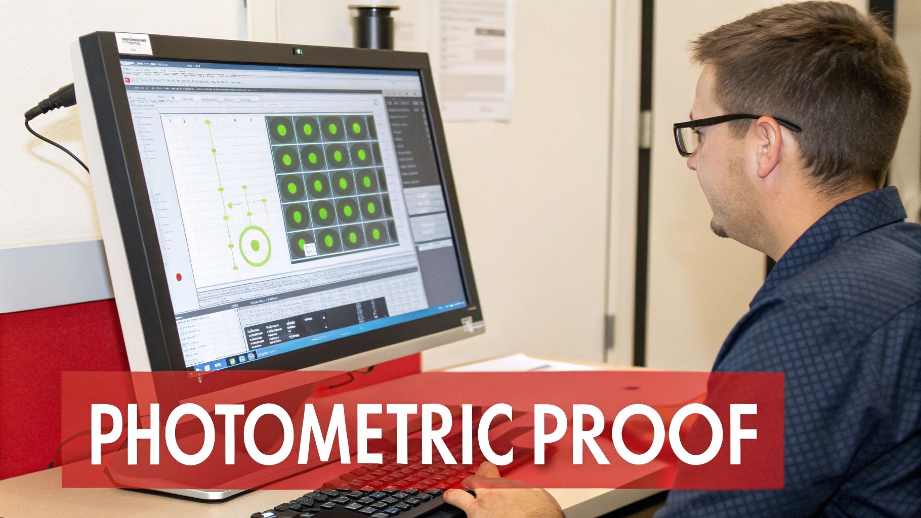
A professional photometric plan is essential for this process. A detailed analysis from a provider like Stetra Lighting validates the design against local codes before construction begins. It provides the foot-candle levels, uniformity ratios, and boundary compliance data required for the permitting process.
Site Analysis and Lighting Strategy
Every successful dark sky compliant lighting project begins with a thorough site analysis. This phase translates architectural drawings and site constraints into a coherent lighting strategy.
A correct initial strategy prevents common design flaws such as poor uniformity, excessive glare, or light trespass. These issues are difficult to correct once integrated into a photometric plan.
The first step is to define the project’s operational needs and regulatory boundaries. Map the entire site, including property lines, structures, pathways, parking areas, and landscape features. A disciplined assessment is critical for establishing a clear lighting hierarchy.

Defining Lighting Zones and Boundaries
Identify all light-sensitive zones before placing fixtures. These areas include adjacent residential properties, natural habitats, or roadways where glare could create a hazard. Mark these zones clearly on the site plan.
These boundaries are non-negotiable and will dictate fixture placement, optics selection, and aiming angles. Establishing a hard property line for light trespass calculations is mandatory. Any calculated light crossing this boundary constitutes a compliance failure.
Establishing the Lighting Hierarchy
A lighting hierarchy prioritizes illumination based on function and safety. Not all areas of a site require the same illuminance levels. Ranking zones allows for intelligent application of light, focusing intensity only where essential.
A standard approach includes:
- Identify Task-Critical Areas: Pinpoint high-priority locations such as entrances, exits, pedestrian walkways, transaction points, and loading docks. These areas have specific, code-mandated illuminance levels for safety and security.
- Define Circulation Zones: Map out parking lots, access roads, and general pathways. These areas require sufficient light for safe navigation but typically have lower foot-candle requirements than task-critical zones.
- Minimize Ambient and Accent Lighting: Areas intended for purely aesthetic illumination should use the lowest possible light levels. Avoid broad, high-intensity floodlighting, which is a major contributor to skyglow.
This tiered strategy treats light as a functional tool, forming the basis of a design that meets safety codes without over-lighting.
Setting Illuminance Targets and Spacing
With lighting zones defined, set specific illuminance targets. These are measured in foot-candles (fc) and are guided by recommendations from the Illuminating Engineering Society (IES).
For example, an office building entrance may require 5 fc, while a main parking area may require a minimum of 1 fc with good uniformity. Refer to specific outdoor lighting foot candle requirements to align targets with IES best practices and local ordinances.
A common mistake is over-lighting a property under the assumption that “brighter is safer.” Excessive light levels and poor uniformity create harsh shadows and disabling glare, which can reduce visibility and compromise safety. The goal is adequate, uniform light, not maximum brightness.
Once targets are set, map preliminary fixture locations, mounting heights, and spacing. Mounting height directly impacts light distribution and required beam angles. Lower mounting heights often require tighter spacing to achieve uniformity. Taller poles can cover larger areas but must be specified carefully to prevent glare and light trespass.
Professional photometric plans are invaluable here. Tools from providers like Stetra Lighting can accurately model these variables, validating the strategy before construction.
Selecting and Specifying Compliant Fixtures
The selection of luminaires is a technical discipline critical to project success and permitting. A proper specification is based on verifiable data from manufacturer spec sheets and photometric IES files. This process removes guesswork and ensures specified hardware will perform as intended.
The starting point for any compliant fixture is its BUG rating. Developed by the IES, this metric (Backlight, Uplight, and Glare) provides a standardized method for quantifying a fixture’s optical performance. For any dark sky project, a U0 rating is non-negotiable. This confirms the fixture produces zero direct uplight.
A U0 rating is only the beginning. Backlight and glare control are equally important for preventing light trespass and maintaining visual comfort. The full BUG rating must be considered. A detailed guide on how fixture design impacts these values is available here: BUG rating system.
Matching Light Distribution to Site Geometry
After confirming the BUG rating, select the correct light distribution type. This determines the shape of the light pattern cast on the ground. Correctly matching the distribution to the application improves uniformity and can reduce the number of fixtures required.
Common IES distribution types include:
- Type II: For long, narrow areas like walkways or paths.
- Type III: For wider roadways or parking lot perimeters, pushing light forward and outward.
- Type IV: Delivers a wide, forward-throw pattern, often used for facade or perimeter wall lighting from a close setback.
- Type V: Creates a circular or square pattern suitable for large, open spaces like parking lot interiors or intersections.
Matching distribution to site geometry is fundamental. Using a Type V fixture on a narrow path wastes light and creates a light trespass issue.
Analyzing Optics and Beam Angles for Precision
Optics and beam angles provide fine-tuned light control. While the distribution type sets the general pattern, specific optics—lenses, reflectors, and shields—shape the beam to control glare and prevent light spill. Fixtures with sharp cutoff optics terminate the light beam abruptly at the edge of the target area.
This level of precision is critical for meeting strict local codes. Poorly shielded residential outdoor lighting is a major contributor to light pollution. It is estimated that 20% to 50% of its light is often aimed upward. By 2018, this waste led the average U.S. household to generate up to 103 pounds of CO2 annually from exterior lighting. The International Dark-Sky Association provides resources on responsible residential lighting.
A common mistake is selecting fixtures based on aesthetics or wattage without analyzing the IES file. The IES file contains the raw photometric data that dictates luminaire performance. Without it, a photometric plan is an estimate.
Developing a Clear Fixture Schedule
The final deliverable is a comprehensive fixture schedule. This document provides unambiguous instructions for procurement and installation, leaving no room for error.
The fixture schedule must clearly define:
- Fixture Type: A unique identifier for each luminaire model.
- Lumen Package: The specified light output required to meet foot-candle targets.
- CCT: The color temperature, typically 3000K or lower for compliant projects.
- Wattage: The fixture’s power consumption.
- Optics/Distribution: The specified IES distribution type and any special optical controls.
- Control Protocols: Details on dimming, sensors, or timeclocks.
To streamline the approval process, consider specifying fixtures certified by the International Dark-Sky Association (IDA). These products have been independently verified to meet dark sky requirements. Modeling IDA-certified fixtures in a professional photometric plan, such as those provided by Stetra Lighting, creates a robust and defensible package for any jurisdiction.
Photometric Modeling and Verification
A photometric plan is the definitive proof that a lighting design meets performance criteria before installation. This process translates fixture specifications, locations, and site geometry into a verifiable simulation. Professional software like AGi32 or DIALux is required to build an accurate model that will withstand regulatory scrutiny.
This step analyzes the performance of the entire lighting system. The objective is to generate measurable data confirming that illuminance levels, uniformity, and light trespass meet local ordinances and IES recommendations. A correct model prevents costly installation errors and facilitates permitting.
Building the Digital Site Model
The first task in a photometric study is to create an accurate digital model of the project site. This typically begins by importing a CAD file from the civil engineer or architect, which provides the foundational geometry of building footprints, curbs, walkways, and property lines.
With the site geometry established, place the selected fixtures. Each luminaire must be positioned with the correct mounting height, setback, and aiming angle as defined in the lighting strategy. It is critical to use the exact IES file for each fixture. This file contains the precise light distribution data required for an accurate calculation.
Generating and Analyzing Calculation Grids
Once the model is built, place calculation grids to measure illuminance. These virtual grids are positioned over key areas like parking lots, sidewalks, and building entries. The software calculates and populates these grids with point-by-point foot-candle (fc) values.
This data allows for verification against several key metrics:
- Average Illuminance: Confirms that minimum light levels for safety and code compliance are met.
- Uniformity Ratios: Expressed as an average-to-minimum or max-to-minimum ratio, this metric quantifies the evenness of light distribution. Good uniformity eliminates dark spots and harsh shadows.
- Light Trespass: A vertical calculation grid placed at the property line must show 0.0 fc, proving no direct light spills onto adjacent properties.
For more information on interpreting these metrics, review our practical guide to photometric analysis. This process is the core of design verification.
Communicating Results with Isoline Reports
Isoline reports provide a clear visual representation of light distribution. These reports overlay contour lines, each representing a specific foot-candle value, onto the site plan. Isoline plots make it easy to visualize how light diminishes from fixtures and to identify potential problem areas.
These reports are effective for presenting to permitting authorities or clients. A clean isoline report showing all light contained within property lines is often the most convincing evidence of a compliant design.
A professional photometric plan from a provider such as Stetra Lighting is a defensible report. It packages the site plan, fixture schedule, calculation grids, and isoline reports into a single document that demonstrates unequivocal compliance.
The real-world impact of this diligence is significant. A growing number of U.S. communities now mandate IDA-certified outdoor fixtures. Tucson, Arizona, achieved a 63% reduction in photopic lumens from its streetlights and a 7% reduction in crime after converting to compliant LEDs. This demonstrates that thoughtful lighting design can enhance both the environment and public safety.
Common Photometric Modeling Mistakes and Solutions
Even experienced designers can encounter issues when modeling for dark sky compliance. The following table outlines common pitfalls and their solutions.
| Common Mistake | Negative Impact | Professional Solution |
|---|---|---|
| Using Generic IES Files | Inaccurate calculations lead to over- or under-lighting upon installation. | Always download and use the specific IES file from the manufacturer for the exact fixture, optics, and lumen package specified. |
| Incorrect Mounting Heights | Alters the intended light distribution, causing poor uniformity, glare, or light trespass. | Verify the mounting height in the model matches the architectural plans and the fixture’s application specifications. |
| Ignoring Light Loss Factors (LLF) | The initial installation is over-lit because the plan fails to account for lumen depreciation over the fixture’s life. | Apply a standard LLF (typically 0.85-0.90) in calculation settings to model realistic, end-of-life performance. |
| Forgetting Vertical Trespass Grids | Lack of objective proof that light does not cross property lines, a common reason for permit rejection. | Place vertical calculation grids at all property boundaries and ensure the report clearly shows 0.0 fc at every point. |
Addressing these details is essential for delivering a responsible, effective, and high-quality lighting design that meets all compliance requirements.
Integrating Lighting Controls for Dynamic Compliance
A dark-sky-compliant design is not complete after fixture selection and photometric approval. Static, always-on lighting is an outdated approach that fails to maximize compliance and efficiency. Integrating adaptive controls is the final layer that ensures a project performs responsibly post-installation.
Controls transform a static design into a responsive system. The principle is to use light only when and where it is needed. Specifying the right controls can dramatically reduce light output during off-peak hours, achieving a deeper level of compliance than a static system can provide.
Specifying Control Strategies
Effective control begins with selecting the appropriate technology for the application. The goal is to automate light reduction, minimizing environmental impact and energy waste without compromising safety.
Common control strategies for compliant projects include:
- Astronomical Timeclocks: These devices track sunrise and sunset times, ensuring lights are active only from dusk to dawn. This is a foundational control for most outdoor lighting projects.
- Motion Sensors: Ideal for areas with sporadic traffic, such as secondary walkways or storage yards. Sensors can be programmed to increase light levels from a dimmed state (e.g., 20% output) to full brightness upon motion detection, then return to the dimmed state after a set period.
- Networked Dimming Systems: These systems provide total site control. Luminaires can be scheduled to dim to a specific percentage at a specific time, such as reducing parking lot illumination by 50% after business hours.
The Critical Role of Commissioning
Specifying controls is only half the process. Proper commissioning is required to verify that the system operates as designed. This post-installation step ensures the connection between the theoretical photometric plan and the physical on-site reality.
Commissioning is not an optional step. It is the final quality assurance check that confirms the correct fixtures were installed and aimed precisely according to the photometric plan. For those new to IES files, an IES viewer can help visualize the data that informs these aiming instructions.
A photometric plan provides precise installation instructions. Commissioning verifies these instructions were followed. Without it, one must assume aiming angles are correct, controls are properly programmed, and on-site performance matches the compliant design submitted for permitting.
A thorough commissioning process must verify several key points. Confirm all aiming angles are set correctly to eliminate unexpected glare or light trespass. Ensure control settings—dimming levels, sensor sensitivity, and timeclock schedules—are programmed to match the operational strategy.
Finally, take on-site foot-candle readings to verify that real-world light levels align with the photometric model. This final step provides definitive proof of a successful, compliant installation.
Frequently Asked Questions in Dark Sky Lighting Design
This section addresses common questions from architects, engineers, and property owners regarding dark sky projects. The information provides practical guidance for achieving a compliant design.
What Is the Difference Between “Dark Sky Friendly” and “Dark Sky Compliant”?
This distinction is critical for design professionals. “Compliant” means a fixture or lighting plan meets specific, measurable technical standards set by an authority, such as the International Dark-Sky Association (IDA) or a local ordinance.
Compliance is proven with objective data. This typically requires a U0 BUG rating, full shielding, and a CCT of 3000K or lower. A compliant design is validated with a professional photometric plan.
“Friendly” is primarily a marketing term. It suggests a product is designed to reduce light pollution but often lacks the formal certification or verifiable IES files required for a permit application. For professional projects, specify products with documented, certified compliance to ensure design approval.
Can I Use Lower-Wattage Fixtures to Be Compliant?
No. Wattage alone does not determine compliance. A low-wattage, unshielded fixture can still produce significant glare, light trespass, and skyglow. Compliance is a function of optical control, not power consumption.
A fully shielded, U0-rated fixture directs all lumens to the ground, preventing waste regardless of its output. The objective is to achieve target illuminance levels, measured in foot-candles, without over-lighting.
The professional approach is to balance a fixture’s lumen package, optics, and placement to achieve required light levels with maximum efficiency. A professional photometric plan from a provider like Stetra Lighting is essential for this process.
How Important Is CCT for Dark Sky Compliance?
Correlated Color Temperature (CCT) is a critical factor. Light with a high CCT (4000K or 5000K) is rich in blue-spectrum light. This short-wavelength light scatters significantly in the atmosphere, which is a primary driver of skyglow.
Blue-rich light is also known to disrupt nocturnal wildlife and human circadian rhythms. Consequently, most dark sky ordinances now mandate warm CCTs.
The most common requirement is 3000K or below. In environmentally sensitive areas or jurisdictions with the strictest codes, amber LEDs (approximately 2200K) may be preferred or required. Specifying the correct CCT is a fundamental component of any compliant design.
Are Motion Sensors Required for Dark Sky Compliance?
While not all ordinances mandate them for every fixture, integrating adaptive controls like motion sensors and timeclocks is a best practice. The guiding principle is to use light only when and where it is needed. Designing without controls is an outdated and inefficient methodology.
Many modern energy codes and local lighting ordinances now require or encourage controls, particularly for areas with intermittent use. A common strategy is to dim site lighting to a low level (e.g., 20% output) during inactive hours. A motion sensor then brings the light to full brightness only when a vehicle or person is detected.
This approach offers significant benefits:
- Maximizes energy savings by reducing hours at full power.
- Minimizes light pollution by reducing total light output overnight.
- Extends the operational life of the luminaires.
Integrating controls demonstrates a commitment to deep compliance, moving beyond simple fixture selection.